Download

1 / 35
360 likes | 393 Views
220 KV SWITCH YARD AT IPCL M.G.C.C. BRIJENDRA AGRAWAL. INDEX. Introduction . 220KV Switch Yard Layout. Switch Yard Equipments Rating of Switch Yard Equipments Interlocking Scheme and PLC Control. INTRODUCTION.

E N D
220 KV SWITCH YARD AT IPCL M.G.C.C BRIJENDRA AGRAWAL
INDEX • Introduction. • 220KV Switch Yard Layout. • Switch Yard Equipments • Rating of Switch Yard Equipments • Interlocking Scheme and PLC Control.
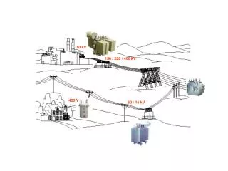
INTRODUCTION • To maintain reliable and continuous supply, IPCL MGCC is kept floating with the MSEB Grid . • In floating mode the grid is always connected to the power plant and import or export of power is always possible, as per the plant requirement. • The major limitation of floating mode is that, the voltage and frequency of power plant is controlled by the grid. So any disturbances caused in the grid due to it’s own load fluctuations will also affect the power plants / import export.
To protect the in-plant generation from grid failure or fluctuations, protective devices are adopted to isolate the grid under abnormal conditions. • The switching and protective equipments along with control devices arranged in a systematic sequence in the outdoor of plants and is termed as ‘Switchyard’.
The 220KV switchyard consists of dual redundant buses namely Bus-I and Bus –II. • Bus-I is used as transfer bus for feeder transformer-I and transformer-II, while Bus –II is main bus. • The 220kv switchyard is divided into five bays (bay-1 to bay-5). • Bay-2 and Bay-3 are the incoming feeders from MSEB i.e. APTA and PEEDAMBE Lines. • Bay –1 and Bay –4 are the two outgoing transformer feeders to the IPCL complex. • Bay 5 is the bus-coupler/bus-transfer bay and it has the provision to couple the two buses.
Each incoming feeder consists of an isolator and SF6 circuit breaker, and connected to two bus isolators to connect to any one of the two main buses. • Each outgoing feeder consists of two bus isolators to connect the feeder to the buses. Further these are connected to a series combination of an SF6 breaker and an isolator. • Each incomer and outgoing feeder is provided with an earth switch (289CA or 389CA) so that a particular section can be made completely dead during maintenance work and ensure safety.
SWITCHYARD EQUIPMENTS SF6 CIRCUIT BREAKER: Circuit breaker is a device capable of making and breaking an electric circuit under normal and abnormal conditions such as short circuit. SF6 circuit breakers make use of the arc quenching and electrical insulating characteristics of SF6 gas. In this breaker the gas flow is puffed by the puffer cylinder, which extinguishes the arc. This principle makes the breaker operation simple, with low breaking noise. The pneumatic operating mechanism, which is operated by air pressure for opening and spring force for closing, is very simple and reliable. These breakers are of single pressure type, and operate on puffer principle wherein the gas flow on the arcing zone is generated by arcing cylinder and piston.
Features of SF6 Circuit Breaker 1. Superior Interrupting Capacity This breaker can successfully interrupt high short circuit current with high rates of rise of re-striking voltage, short line faults, out of phase faults, capacitive current without generating dangerous over voltages. 2. Low Operating Noise Since the breaker is sealed off from atmosphere there is no gas exhaust noise during operation. 3. Simple Construction & Compact Size Single break at 245KV coupled with non-exhausting gas design makes the breaker structure simple and compact. 4. Easy To Install and Maintain As the construction is simple, installation and inspection is very easy and since deterioration of SF6 gas is negligible, the maintenance of these breakers is easy and the interval is very long.
CVT: The capacitor voltage transformer consists of a capacitive potential divider and an inductive medium voltage circuit. The inductive part is immersed in the mineral oil and hermetically sealed with an air cushion inside the steel tank. One, two or three units are mounted on the steel tank and used as capacitive potential divider. The CVT unit must always be kept vertically and under no condition be kept horizontally.
CT: The CTs in switchyard are designed for high voltages with porcelain insulators which can withstand up to 245KV. The CT unit is a hermetically sealed, oil filled unit with nitrogen filled in the expansion chamber at the top. This prevents changing and filtration of oil frequently and hence reduces maintenance. The primary terminals consist of tin-plated special 30mm diameter copper rods for currents up to 1600A and 40mm for currents up to 2400A.
SWITCHYARD TRANSFORMER: The switchyard transformer is used to step-down the grid voltage of 220KV to 11KV. Features of the Transformer. Variable capacity: The capacity of the transformer can be increased if an effective cooling media is provided to dissipate the generated heat. This needs no change in the design features of windings. The transformer is provided with two rated capacities of 25MVA and 33MVA. Two types of cooling systems are also provided corresponding to the two capacities. ONAN - Oil natural Air natural type in which the transformer is cooled with natural air by the radiators. ONAF – Oil natural Air forced cooling is provided using fans to blow air through the radiators. This helps in effective heat dissipation and the transformer capacity can be increased upto 33MVA.
On Load Tap Changer: Voltage control in a supply network is essential for several reasons, including:- The adjustment of consumers voltage within the statutory limits. The control of the kW and KVAr flow over a line interconnecting two generating stations. Seasonal (5-10%), daily (3-5%) or short period (1-2%) regulation of the voltage of various parts of a network in accordance with cyclic changes of load distribution. Much of this regulation is done by altering the ratio of transformation by tapping the windings to alter the number of turns. This process is termed tap changing. It may be done when the transformers are out of circuit (particularly with short-periodand daily load cycles requiring voltage adjustment) or when on load.
The latter condition is more complicated and done with on-load tap-changers. The tap changer is used for changing the voltage from -20% to +10% in steps of 1.25%. ISOLATORS: • Isolator is used as a switch for positive isolation of supply to a particular section. • It can operate only on no load as it does not have any specified breaking or making capacities. • It cannot be used for breaking load currents also. It is sometimes used for breaking charging currents of transmission lines. • Isolators are normally used along with breakers. They are needed on the supply side of the circuit breaker to ensure complete isolation of the breaker from live parts for allowing maintenance work.
Isolators also have three identical poles like a breaker but does not have any arrangement for arc quenching as they are for no load operation. Isolator Operation A Local/Remote switch gives the control mechanism for operation of the isolator. Local Mode On/Off From Local control cabinet (Motor Operated). Manual (By manually rotating the isolator). Remote Mode Control from the control panel in switchyard (Motor Operated). Control from PLC through PLC IN/OUT selection switch (Motor Operated).
LIGHTNING ARRESTOR • Over voltages occur on the power systems for few microseconds. They are characterized by high rate of rise and high peak value which are dangerous for insulation. • Lightning surges originate on transmission lines or outdoor equipments. The wave travels along the conductors and reaches the substation. • Lightning arrestors or surge arrestors are connected between phase and earth in substation, distribution system, near the transformer terminals and near the terminals of large rotating machines. Surge arrestors discharges the excessive surge voltage to ground and hence protect the insulation system.
RATING OF SWITCH YARD EQUIPMENTS • BUSBARS: Rated voltage 220KV. Rated current 600A. S.C. current 40KA for 1 second • CVT: Rated Voltage 220kv. Max. Service Voltage 245kv. Type Designation WS 245 N. No. of secondary 2. Rated secondary Voltage 110V.
CT: Rated Voltage 220kv. Max. Service voltage 245kv. Type Designation IMB. • SF6 BREAKER: Type designation ELF 245. Rated voltage 245KV. Symmetrical breaking current 40KA. Making current 100KA. Total break time Less than 60ms. Total closing time 130ms. Pole to pole distance 4000mm. No. of auxiliary contacts 15 NO+15 NC. Closing blocking pressure 17bar.
Opening blocking pressure 16.7bar. Weight 2500kg. • ISOLATOR: Operation Center break motor operated. Reference Standard IS 1818 1972. Max. Design Voltage 245kv. Frequency 50Hz. Current rating 630A. Conducting Material Aluminum alloy. Rated motor output 0.5 HP, 415 v, 3-Phase, A.C.
SWITCHYARD TRANSFROMER: Rated Capacity 25/33MVA. Voltage ratio 220/11 kV. P.U. impedance R – 0.0240. X – 0.5995 on 100MVA base. • NGR 7.273 ohms on 11kv side. Vector group Ynyn0. Tap changer On load tap changer -20% to +10% in steps of 1.25%.
INTERLOCKING SCHEME AND PLC CONTROL The operation of switchyard equipments like isolators, circuit breakers can be done in any of the following ways: Operation from local control cabinet (for isolators only) Remote operation from control panel in the 220KV switchyard. Remote operation from ECS or PLC A local/remote selection switch is provided, and if local mode is selected then the operation is possible only from control cabinet and when remote mode is selected the operation is possible from control panel or from ECS.
Each isolator has to satisfy a series of interlocks to get operated. Once all the interlocks are satisfied the interlocking relay of that particular isolator gets energized and operation of the isolator is possible.. The following are the interlocks to be satisfied for different isolators: Line isolators can be closed if the corresponding breaker and earth switch are open. For isolator 289C to operate following condition must be met : 289CA (Earth switch) - OPEN. 252 (Circuit breaker) - OPEN.
Bus-1 isolator can be operated if bus-2 isolator is open and corresponding breaker is open. However Bus-1 and Bus-2 isolator can be operated at a time if both the main buses are coupled i.e., Isolator 589A, 589B and Breaker 552 are closed. For 189A to operate to operate either of the following conditions must be met : 189B - OPEN. 152 - OPEN. 189D - OPEN. (OR) II. 552 - CLOSE. 589A - CLOSE. 589B - CLOSE. 189B - CLOSE. 189D - OPEN.
For transfer bus isolators 189D or 489D, operation is possible only if, all the isolators connected to corresponding bus are open and Isolators 589A, 589B are closed and Breaker 552 is open. By closing the transfer bus isolator the bay breaker can be taken out for maintenance. For 189D to operate: 189A - OPEN. 289A - OPEN. 389A - OPEN. 489A - OPEN. 552 - OPEN. 589A - CLOSED. 589B - CLOSED.
Earth switches are mechanically and electrically interlocked with the corresponding line isolators so that they can be closed only if line isolators are open. • Bus-coupler bay isolator 589A or 589B can be operated if bus-coupler bay breaker 552 is open. • Operation from ECS: Operation of isolator and breakers is possible by PLC in/out selection switch. If PLC is selected then all the controls from control panel are de-activated
BUSBAR PROTECTION SCHEME: • The bus bar protection scheme is divided into three zones namely Zone-1, Zone-2 and check Zone. • Zone-1 takes care of faults on Bus-I and Zone-2 for Bus-II. • Check Zone is used for counter checking the fault before giving the trip command to the breakers. • The bus bar protection consists of two CTs, one on each incomer on the MSEB side. Corresponding to this there are two other CTs one on each outgoing feeders on MGCC side.
CT SELECTION: CT selection is required so as to ensure that if any fault occurs on a bus, then that particular bus should be isolated and not the other bus. This is achieved through isolator positions, which determine the incoming and outgoing feeders, connected to a particular bus. LOCAL BREAKER BACK UP The bus bar protection system is backed up by LBB, which operates after a specified time delay. If bus bar protection fails, over current relays of individual feeders will operate and after a the specified time delay if O/C and E/F relay also fails then permission is given to the LBB of individual feeders which trips all the incoming and outgoing feeders of that particular bus. But if the bus coupler bay isolators are closed, then the LBB of the bus-coupler bay will also operate and after the specified time delay all the incoming and outgoing feeders are tripped. This will completely make the whole switchyard dead and gives a redundant backup protection.
220KV INCOMER PROTECTION SCHEME: The 220KV incomers are provided with the following protections: • O/C and E/F protection. • Under frequency protection. • Reverse power protection (Only alarm). The 220KV incomer consists of CT-T01 and CVT (On Y-phase only) for giving protection and metering. The CT-T01 is a 5-core CT and is used for the following functions. Core-1 is used for metering and for reverse power protection. Core-2 is used for O/C & E/F protection.
Core-3 for Local breaker backup, Core-4 and core-5 are used for bus bar protection on MSEB side. O/C AND E/F PROTECTION The core-2 of CT-T01 is used for this protection. The secondary of this CT is given to O/C and E/F relay. In case of fault on incomer this relay gets energized and initiates the master trip relay 86A and given annunciation through its auxiliary relay 51/X or 51N/X. The relay 86A performs the following actions: 1. Gives a trip command to trip coil-2 of the corresponding breaker on the line (252 or 352). 2. Blocks closing of the breaker. 3. Operates its auxiliary relay 86A/X. 4. Operates its trip circuit supervision relay 27A1 (VAX 21).
5. Gives clearance to its LBB relay. UNDER FREQUENCY PROTECTION The under frequency relay is a microprocessor based relay. The PT supply of incomer-1 is given as input to this relay. This relay has four stages of operation. It uses a microprocessor for signal processing and is fully programmable. Each frequency stage is configurable for over frequency or under frequency protection. The operation of the relay is based on set frequency value (f> or f<), or the rate of change of frequency (df/dt), or on a combination of both the parameters.
Settings Of Frequency Relay STAGE DESCRIPTION CODE 1 F<48.5Hz & df/dt=2Hz/sec-START 1 Time delay=0.3sec(252/352)-TRIP 2 2 F<47.8Hz - START 3 T=0.15sec - TRIP 4 3 F<48.5Hz & df/dt=2Hz/sec 5 T=0.15sec on relay - ALARM 6 4 F<48.4Hz - START 7 T=5sec on Annunciation panel 8
REVERSE POWER PROTECTION This protection is provided only to give alarm but not a trip. The relay PPX111 or 32 is used for this protection. The inputs for this relay are line voltage and current given from the PT supply of the incomer-1 and CT-T01 of the incomer-1.
25/33.3 MVA TRANSFORMER PROTECTION SCHEME: The grid transformer has been provided with the following protections: 1. Transformer differential protection. 2. REF protection on primary and secondary sides. 3. O/C relays with LBB. 4. Backup earth fault or standby earth fault protection. 5. Bucchholz relay, Winding temp. , Oil temp. and tap changer out of step protection. 6. Intertripping.
The transformer incomer consists of a 6 core CT-T02 on the 220KV side for metering and protection purposes. Core-1 is used for differential protection. Core-2 for REF protection, Core-3 for O/C protection along with LBB. Core-4 for metering. Core-5 and core-6 for bus bar differential protection. Similarly, the transformer has a CT on 11KV side, which is used for differential protection and REF protection on secondary side. Also there are CTs in the neutral of the transformer for REF and backup earth fault protection. Apart from these external fault protections the transformer is also has protections for internal faults, which are taken care by bucchholz relay trip, O.T and W.T trip and tap changer out of step protections.
INTERTRIPPING The grid transformers are provided with inter tripping feature. This feature ensures that both upstream and downstream breakers of the transformer are to be operated in case of fault on either side. This ensures complete isolation of the transformer from the fault and prevents back feeding of the fault and no load losses.