Download
1 / 30
300 likes | 331 Views
Detailed analysis of the MWPCs for the LHCb muon system, including specifications, gas properties, ionization statistics, and choice of parameters. Recommendations for optimizing timing efficiency and spatial resolution.

E N D
MWPC requirements Engineering Design Review April 16th 2003 Werner Riegler CERN Werner Riegler CERN, April 16th, 2003
LHCb Muon System 5 muon stations, one in front (M1), 4 behind (M2-M5) the calorimeter A muon trigger requires the coincidence of hits in all 5 stations within the bunchcrossing time of 25ns in a certain spatial window that selects the muon momentum. Granularity 1x2 cm to 10x20cm. Werner Riegler CERN, April 16th, 2003
PNPI proposal: 1.5/2mm pitch, 5mm full gap, 30m wire, Ar/CO2/CF4 gas mixture, double gap, wire pads, cathode pads Wire pad chamber for LHCb muon system, B. Botchine, A.Kashchuk, V. Lazarev, N. Sagidova, A. Vorobiev, A. Vorobyov, LHCb-2000-003 Detector physics and performance simulations of the MWPCs for the LHCb muon system, W. Riegler, LHCb-2000-060 Crosstalk, cathode structure and electrical parameters and of the MWPCsfor the LHCb muon system, W. Riegler, LHCb-2000-061 Werner Riegler CERN, April 16th, 2003
Detector 2 chamber layers are connected into one frontend. 4 layers of MWPCs are combined into one station. Werner Riegler CERN, April 16th, 2003
Difference to ATLAS, CMS The ATLAS Cathode Strip Chambers are intended for position resolution. Amplifier peaking time 80ns, bipolar shaping, ‘crosstalk intended’ on cathode strips for center of gravity. The CMS Cathode Strip Chambers are intended for position resolution (cathodes strips) and timing (wires). Cathode amplifier peaking time 100ns, wire amplifier peaking time 30ns. The LHCb MWPCs are intended for highly efficient timing within a certain spatial granularity at the LVL0 trigger. Amplifier peaking time of 10ns, pulse width<50ns, unipolar shaping, low crosstalk. Since crosstalk is RinCpp and since (20 MHz) is high we have to minimize the pad-pad capacitance Cpp and amplifier input impedance Rin. Because we want unipolar shaping we need a baseline restorer in the front end. Werner Riegler CERN, April 16th, 2003
Geometry and Fields Volt /cm Pitch 2 mm Gap 5 mm Wire 30 m HV 2750 V Cathode field 6.2 kV/cm Wire field 262 kV/cm cm Werner Riegler CERN, April 16th, 2003
Gas Properties For 10 GeV muons we expect about 42/45 clusters/cm 0.24/0.22 mm 2.35/2.38 e-/cluster, 99/107 e-/cm Drift velocity of 90-100m/ns is ‘saturated’ meaning that a small change in electric field does not affect the time resolution. Werner Riegler CERN, April 16th, 2003
Electron Drift Isochrones (ns) 2mm pitch 1.5mm pitch 5 5 10 10 15 15 20 20 25 30 25 30 Average arrival of electrons is 30ns. It seems that time resolution can always be improved by reducing the wire pitch, BUT Werner Riegler CERN, April 16th, 2003
Ionization Statistics Because the primary ionization statistics I.e. Poisson distributed cluster number =exponentially distributed distance between clusters around average of 0.23mm the Time resolution doesn’t improve for pitch <1.5mm. This is a fundamental limit of time resolution for an MWPC at 1bar. Werner Riegler CERN, April 16th, 2003
Choice of Parameters and Specifications • Wire Pitch • Gas Gap • Wire Diameter Werner Riegler CERN, April 16th, 2003
ra: anode wire radius Va: anode wire voltage : ion mobility q: charge per hit R: hits/cm2 1) rc=(s/2) Exp(h/s) Equivalent cathode radius 2) Ea=Va/(ra ln(rc/ra)) Anode wire surface field 3) Ec= Va/(s ln(rc/ra)) Cathode surface field 4) t0= ra2 ln(rc/ra)/(2Va) Signal tail 5) I(t)= q/2ln(rc/ra) 1/(t+t0) Induced Signal 6) Q(t)=q/(2ln(rc/ra))*ln(1+t/t0) Induced charge (ions) after time t 7) V=Rsh2q ln(rc/ra)/(4Va0) Voltage drop due to space charge effect 8) Ec/Ea= ra/s Ratio of wire to surface field (3)/(4) 9) Va= Eara (h/s+ ln(s/2 ra)) Voltage for a given surface field (1),(2) 10) G = [V/(ra ln(rc/ra)Emin)]^[Vln2/ (ln(rc/ra)dV)] Gas Gain, Emin, dV Diethorn param. Werner Riegler CERN, April 16th, 2003
Choice of Wire Pitch At fixed gap 5mm, gas gain 0.75*105 and wire diameter 30m: Increasing the pitch 1.522.5 mm is HV 3.152.752.53 kV/cm good Cathode surface field 8.246.24.95 kV/cm good Wire surface field 262262262 kV/cm ------ Sensitivity to imperfections good Signal tail t0 1.51.51.5 ------ Signal integrated after 10ns 12.714.615.8 % bad Pulse width, last electron: 3030 30 ns ------ Time Resolution bad dV @ 1MHz (300e-/cm) 202734 V bad Cathode charge distribution ------ Werner Riegler CERN, April 16th, 2003
Choice of Gas Gap At fixed pitch 2mm, gas gain 0.75*105 and wire diameter 30m: Increasing the Gap 456 mm is HV 2.442.753.06 kV/cm bad Cathode surface field 6.26.26.2 kV/cm ------ Wire surface field 262262262 kV/cm ------ Sensitivity to imperfections good Signal tail t0 1.51.51.5 ------ Signal integrated after 10ns 16.414.613.1 % bad Pulse width, last electron: 2430 36 ns bad dV @ 1MHz (300e-/cm) 142747 V bad Cathode charge distribution bad Werner Riegler CERN, April 16th, 2003
Choice of Wire Diameter At fixed pitch 2mm, gas gain 0.75*105 and gap 5mm Increasing Wire Diameter 103050 m is HV 2.232.753.11 kV bad Cathode Surface Field 4.336.27.5 kV/cm bad Wire Surface Field 552263192 kV/cm good Sensitivity to imperfections ----- Signal tail t0 0.241.53.4 ns bad Signal integrated after 10ns 231510 % bad Pulse width, last electron: 3030 30 ns ----- dV @ 1MHz (300e-/cm) 392722 V good Wire Stability good Cathode charge distribution ----- Werner Riegler CERN, April 16th, 2003
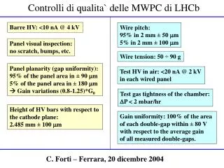
Sensitivity of the performance on chamber imperfections • The drift velocity is saturated I.e. it has a very weak dependence on the electric field. Therefore we mainly worry about gas gain variations that can move the working point within the plateau. • If G0 is the nominal gas gain, we want the gas gain in 95% of the area of a single gap to be within G0/1.25 and G0*1.25 I. e. between 0.8G0 and 1.25G0. • The remaining 5% of the area should have a gain within a factor 1.5 I.e. • between 0.67G0 and 1.5G0 • A gain change of a factor 1.25(1.50) corresponds to Voltage change of 34(62)V on top of the 2750V corresponding to 1.25(2.25)%. • The gas gain changes by a factor 1.25(1.5) if the wire surface field changes by 1.25(2.25)%. • What chamber imperfections are allowed in order to keep the wire surface field within 1.25(2.25)% ? Werner Riegler CERN, April 16th, 2003
Measured Efficiencies 40V 40V 60V 60V Wires Cathodes Werner Riegler CERN, April 16th, 2003
The entire wire plane has to be within 370(490)m in y direction. The cathode - cathode has to be within 113(202)m. Werner Riegler CERN, April 16th, 2003
y x A single wire has to be within 350(450)m in y direction. A single wire has to be within 163(293)m in x direction. Werner Riegler CERN, April 16th, 2003
Specifications Keeping everything else in perfect position, for a single gap chamber with 5mm gap, 30m wire and 2mm pitch, the allowed offset in order to find a wire surface field difference of 1.25(2.25)% is • gap:113 (202) m • single wire X:163 (293) m • single wire Y:350 (450) m • wire plane Y: 370 (490) m Which we translate into specifications of • gap: 95% in 90m 1% 5% in180m 2% • pitch: 95% in 50m 0.35% 5% in100m 0.7% • wire y-offset: 95% in 100m0.1% 5% in200m 0.4% • wire plane y-offset: 95% in 100m0.1% 5% in200m 0.42% • Added in squares: 1.07% 2.2% Werner Riegler CERN, April 16th, 2003
Specifications Moving everything in the worst direction: • gap: -90m1.00% • wire plane: +100m 1.12% • single wire Y:+100m 1.14%1.38%1.14% • single wire X:-50m/0/+50m1.18% 2.10% 1.18% Werner Riegler CERN, April 16th, 2003
Guard Wire Without a guard wire the wire surface fields and gas gains on the edge wires would be 301 269 263 262 … kV/cm 11 1.2 0.8 0.7 … x 105 Using a 200m diameter guard wire at the same pitch of 2mm gives 70.4 251 260 262 … kV/cm 0.0012 0.4 0.6 0.7 … x 105 Werner Riegler CERN, April 16th, 2003
Wire Tension, Instability We use a 30m wire with 60g tension (half of the elastic limit). The maximum allowed wire length for a gas gain of 106 would be 65cm. We use a maximum wire length of 30cm i.e. we are safe. Wire sag is not an issue since the wires are vertical. We specify that no wire should have a tension of less than 50g. Werner Riegler CERN, April 16th, 2003
Many ‘different’ chamber types with different capacitance, grounding, signal flow … Werner Riegler CERN, April 16th, 2003
Crosstalk Specification Double gap chamber 95% efficiency if the threshold is set to 30% of the average signal. 99% efficiency if the threshold is set to 20% of the average signal. In order to have a double gap chamber well within the plateau we want to be able to use a threshold of 15% of the average signal. Werner Riegler CERN, April 16th, 2003
Specification of Capacitive Crosstalk • Crosstalk due to ‘direct induction’ is ‘irreducible’ and given by our choice of 2.5mm cathode-wire distance. • In case of a hit on a given pad, the probability that a neighboring pad fires should be < 5%. • We want to be able to operate the chamber at a threshold of 15% of the average muon signal. • This specifies the ‘crosstalk ratio’ I.e. the fraction of signal allowed signal on a neighbor pad: • Assuming 95% of the signals within 3x average the crosstalk ratio has to be < 15%/3 = 5%. Werner Riegler CERN, April 16th, 2003
Pads, Readout Traces 0.5mm guard trace between pads 0.4mm gap between pad and guard trace 1.6mm boards in case of traces 0.8mm board otherwise 0.25mm readout traces 0.25mm guard traces at 0.25mm pitch We carefully studied readout and guard trace geometries to minimize crosstalk. Calculations were done with MAXWELL. Werner Riegler CERN, April 16th, 2003
Crosstalk Simulation We modeled each chamber including all pads, mutual capacitances, amplifiers … Werner Riegler CERN, April 16th, 2003
Crosstalk Simulation 35-95 pF Cathode Pad Capacitance 15-209 pF Wire Pad Capacitance maximum pad-pad capacitance 3.95 pF maximum crosstalk 2.27 % maximum opposite sign crosstalk - 7.31 % Werner Riegler CERN, April 16th, 2003
Crosstalk Measurement Crosstalk on M2M3R1 prototype at very high gas gain (1.8 x 10⁵) is still <5%. Werner Riegler CERN, April 16th, 2003
Crosstalk, Stability • We have a very good clue and understanding of the ‘smooth RC’ behavior of the chambers. • Since we have large capacitances (up to 220pF), even very small voltage drops due to parasitic inductances and ‘bad’ grounding can cause problems. • E.g. a 20V signal on the ground together with a 200pF capacitance fires the 5fC threshold. • Although we had every chamber type in stable conditions in a testbeam the frontend-board to chamber connection has still to be properly engineered. Werner Riegler CERN, April 16th, 2003