Download
1 / 17
170 likes | 278 Views
This technical report outlines the LHCf experiment aimed at measuring photons and neutral pions in the very forward region of the Large Hadron Collider (LHC). The proposed setup includes two independent detectors with tungsten scintillator fibers and silicon strips. The document highlights key physics goals, operational safety issues, and the necessary modifications to the LHC infrastructure. Scheduled for installation prior to the LHC's startup in May 2007, this experiment aims to enhance our understanding of high-energy interactions in particle physics.

E N D
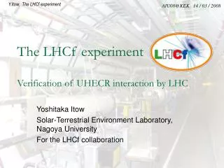
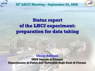
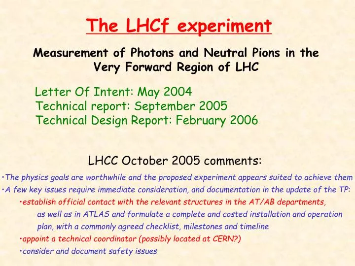
The LHCf experiment Measurement of Photons and Neutral Pions in the Very Forward Region of LHC Letter Of Intent: May 2004 Technical report: September 2005 Technical Design Report: February 2006 LHCC October 2005 comments: • The physics goals are worthwhile and the proposed experiment appears suited to achieve them • A few key issues require immediate consideration, and documentation in the update of the TP: • establish official contact with the relevant structures in the AT/AB departments, • as well as in ATLAS and formulate a complete and costed installation and operation • plan, with a commonly agreed checklist, milestones and timeline • appoint a technical coordinator (possibly located at CERN?) • consider and document safety issues
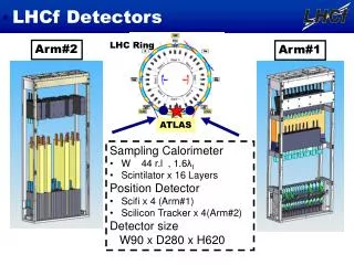
Experimental Method:2 independent detectors on both sides of IPX Detector I Tungsten Scintillator Scintillating fibers Detector II Tungsten Scintillator Silicon mstrips INTERACTION POINT 140 m 140 m Beam line • Redundancy • Background rejection (especially beam-gas) • Physics single diffractive/double diffractive
Y Chamber Detector location
Detector #1: transverse projection E5780 E5780 E5780 E5780 Hamamatsu MA-PMT for scintillating fibers Scintillating fibers R7400U R7400U R7400U R7400U PMTs for WLS fibers WLS fibers to readout plastic scintillators 4cm 130 mm 3cm 2cm BEAM AXIS 90 mm
Detector #2 6.4 cm Silicon 6.4 cm W + Sci 4 cm Si 3 cm Sci+W Si Si Si 2 cm SciFi are replaced by silicon mstrips 64x64 mm2 Pitch 160 mm 3 double layers (x-y) 1 double layer in front of the calorimeter
The TAN for the luminosity monitor Photos taken On April 25th, 2005 At CERN
Few general comments • Choice of the Interaction Region • IP8 (LHCB) or IP1 (ATLAS) were identified in 2004 • IP1 was definitely chosen by LHCC in October 2005 • Detectors on both sides symmetrically wrt interaction point • LHCf will be installed before the LHC startup (May 2007) • ‘Ideal’ running conditions: • 43 Bunches • Low luminosity (~1030 cm-2s-1) • ≤ 1 year data taking period • Detectors will be moved up and down by remote control • (during beam setting operations)
Operations required on the LHC infrastructures (1) • Modifications of the TANs (before February 2006?) to: • install manipulator remotely controlled • install minicrates for the electronics • install additional shielding on top of the TAN to protect the detectors in ‘parking position’
Manipulator Shield Minicrate Mechanical drawings of interconnections between TAN and manipulator, minicrates and shielding should be done a.s.a.p. to drill holes before TAN installation in tunnel
Operations required on the LHC infrastructures (2) • Modifications of the TANs (before February 2006) to: • install manipulator • install minicrate for the electronics • install additional shielding on top of the TAN to protect the detectors in ‘parking position’ • Cables (to be pulled before February 2006?): • Power lines • DAQ lines (optical fibers) • Analog signals for trigger • Slow controls • Cables for manipulator • Water cooling for the electronics • 220 V ?
LHCf and LUMI monitor inside TAN LUMI monitor inside TAN is beyond LHCf (replacing 4th copper bar) IP1 Cu Bar / ZDC LHCf Cu Bar / ZDC LHCf Lumi Lumi LHCf 54 X0 thickness Beam Pipe is shaped to have a projected thickness of 1 X0 on 10 x 10 cm2 region LUMI Monitor see different thickness of material depending on the LHCf position (one of the LHCC concerns!!!!) We are studying the problem of the LUMI calibration together with W.C. Turner and his group from LBNL
The next steps… • Technical coordinator at CERN starting from December 2005 • Strict contact with TS/LEA and LEMIC • Strict contact with Atlas experiment • Electronics crates in USA15 • Cables in the Atlas zone • Trigger • Demande Installation Cables (DIC) in preparation • Engineer Change Request (ECR) in preparation for all the • TAN and LHC related activities
The calorimeter in the test experiment Scintillating Fibers Scintillators plane Size: 9.6 cm x 29 cm x 55 cm