Progress Update on Muon Tracking FEE for PHENIX: Status, Results, and Future Plans
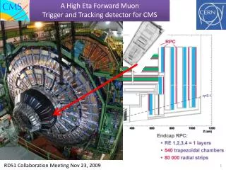
This presentation outlines the latest developments in the Muon Tracking Front-End Electronics (FEE) for the PHENIX experiment. Key topics include the project's scope, current status, prototype results, and the production schedule. The project aims for 100-micron position resolution with detailed specifications on electronics, tracking chamber interfaces, and associated mechanical structures. The presentation highlights achieved milestones, critical issues addressed, and an overview of future work, including testing and calibration to ensure system performance.

Progress Update on Muon Tracking FEE for PHENIX: Status, Results, and Future Plans
E N D
Presentation Transcript
Muon Tracking FEE presentation to the PHENIX Muon Arm Technical Advisory Committee R.E. Mischke Los Alamos 10 September, 1999
Outline • Scope of Project • Status • Results from CROC prototype • Schedule • Production cost • Summary
Scope of Project • Electronics • tracking chambers to Phenix interface • Associated Mechanical Structures • Power and Grounding • Ancillary Systems • Installation • Calibration
System components CROC CNTL 8 CPA 2 AMUADC Clink DCM FPGA ARCnet Chamber cathodes Glink T&FC 24” cable
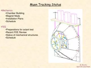
Mechanics Status and Schedule • In-magnet mechanics • design and review complete • fabrication in process (AMC at NMSU) • deliveries on 1 Jan and 1 May, 2000 • Platform • design underway (B. Archuleta, J. Archuleta) • installation in Feb, 2000 • Cable routing • preliminary design complete
FEE Design Spec • Want 100 micron position resolution from 0.5 cm cathode strips read out at 1 cm • input cap 0 - 150 pF; typical charge 80 fC • noise requirement of 0.7% or 0.5fC (3125 e) • dynamic range 11 bits (0.8fC to 800fC) • gain: 3.5 mV/fC • typical spacing of pulses is 100 ms • pulse rise time 500 ns • decay time less than 12 ms • four samples per pulse • reasonable power-up defaults; calibration control
CPA Status • Reviewed in Dec 98 - Several Issues • Additional measurements in Jan 99 • power supply sensitivity, linearity, channel to channel gain variations, recovery from overload, cross talk, dynamic range • Modifications • fix serial out, change default offset DAC • Final review Apr 99 • Production order Jul 99 • Delivery Oct 99
CROC Status Prototype board is being extensively tested repaired prototype CPA chips are used power-up defaults are unsatisfactory load serial strings via CPA test stand analog sections can be studied without CNTL board mounted in chassis with backplane test chamber and 24” cable used as a load and to inject signals
Results Gain: 2.5V/764mV/1pF = 3.3 mV/fC typical noise values for 64 CPA channels 0.6mV RMS (no load) 2 mV RMS (with test chamber) setup not optimal - additional testing planned no HV, jumper wires, temporary grounds, incomplete shielding, small scale, no digital Anode pulse - 1.3 V out/ 7.3 V in BLR (base line restore) concerns
CNTL and Glink Status • CNTL board • prototype almost assembled • initial FPGA code written • Glink/Clink • design in layout • cable tests underway soon
Status of Other Items • Calibration • pulsing of anodes has been shown to work • system design just beginning • Everything Else (non-critical items postponed for now) • LV power • Arcnet • T&FC and DCM connections • Ancillary systems
Agreement with NIS4 • will continue with present design of electronics through prototyping • will support mechanical design as resources permit • will not oversee electronics production, but will be available for consultation • expect to complete work by 31 October
Schedule I CPA chips production chips expected first chips will be tested in Los Alamos remaining chips will be tested at BNL (Chi) CPA test stands (two from ORNL) modify for production (McGaughey) Stand alone ARCnet existing capability to inject serial strings (Hoover) implement for prototypes via spare CNTL (Liu) 31 Oct 5 Nov Jan, 00 15 Oct 1 Oct
Schedule II CROC board complete testing of analog portion (Cafferty) test digital part (awaits CNTL board) order corrected prototype board final tests with production CPA chips CNTL board (Robinson, Thornton) initial checkout and loopback tests communication with AMUADC T&FC and DCM links 15 Sep 10 Oct 1 Nov 10 Nov 15 Sep 10 Oct 20 Oct
Schedule III FEM review target date is early November chain test with production chips is prerequisite including data with real signals from test chamber Production of CROC and CNTL boards early parts orders in preparation (Hart) place most orders if funds available allow 3 1/2 months for board production 10 Nov 15 Sep 15 Nov Mar, 00
Schedule IV Board test stands Develop design (Liu) Assemble at LANL for use with prototypes Ready for production testing at BNL (Liu, Hoover, +) Calibration Begin detailed design (Leitch) Available for system checkout 1 Oct 1 Nov Mar, 00 1 Oct Jun, 00
Schedule V Glink/Clink (Echave, S. Archuleta) complete cable tests prototype boards packaging and location Power complete specs (Hart) Slow Controls (Hoover) Ancillary Systems (Pate) 30 Sep 31 Oct 30 Nov 1 Oct Feb, 00 Feb, 00
Schedule VI Assembly and Installation (Sondheim) detailed plans need to be developed test and assembly at BNL Milestone targets look reasonable 1 Mar boards available 14 Apr install 1st CRA 11 Jul install last CRA 1 Nov Mar, 00 (Cross rib assembly)
Summary • Performance of analog portion of prototype encouraging • design specs have been met (with caveats) • No show-stoppers expected with digital portions • Most areas of project are being addressed • Schedule is aggressive, but not unreasonable • Production cost estimate conservative