Download
1 / 11
110 likes | 147 Views
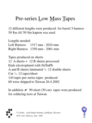
Pre-series L ow M ass T apes. 12 different lengths were produced for barrel 3 harness 50 m Al/ 50 m kapton was used Lengths needed: Left Harness 1317 mm - 2024 mm Right Harness 1350 mm - 2061 mm Tapes produced on sheets 12 A sheets + 12 B sheets processed

E N D
Pre-series Low Mass Tapes 12 different lengths were produced for barrel 3 harness 50 m Al/ 50 m kapton was used Lengths needed: Left Harness 1317 mm - 2024 mm Right Harness 1350 mm - 2061 mm Tapes produced on sheets 12 A sheets + 12 B sheets processed Ends electroplated with Ni/SnPb A and B sheets laminated 12 double sheets Cut 12 tapes/sheet 144 tapes pre-series tapes produced 60 were shipped to Taiwan 26.4.2002 In addition 90 short (30 cm) tapes were produced for soldering tests at Taiwan V. Cindro, Jožef Stefan Institute, Ljubljana, Slovenia SCT week, Valencia, June 2002
Acceptance: Underetching of lines (reduction of average metal trace width) shall be less than 100 microns. Conductor width reduction shall not exceed 30 % of the nominal conductor width. Conductor spacing shall not be reduced by more than 30 % due to conductor edge roughness, spikes, etc. Line resistance shall be smaller than 0.15 /m for 4.5mm lines and 1.7 /m for 0.5 mm lines. Inter line resistance shall be greater than 100 M. Leakage current < 100 nA at 500V There shall be no lifted Al lands on the delivered tapes. Al thickness shall not be changed by the process by more than 10 %. Adhesive flow on coverlay edges shall not be more than 2mm. Electroplated surface shall be solderable in accordance with IEC 68-2-20. Plating adhesion shall be tested in accordance with IPC-TM-650, method 2.4.1. using a strip of pressure sensitive tape. Misalignment of lines on top and bottom layer shall be smaller than 0.2 mm in laminated area. The yield of the production of double layer tapes shall be greater than 80 %. For small quantities, lower yield figures can be agreed. V. Cindro, Jožef Stefan Institute, Ljubljana, Slovenia SCT week, Valencia, June 2002
Optical inspection (now at ELGO-LINE) V. Cindro, Jožef Stefan Institute, Ljubljana, Slovenia SCT week, Valencia, June 2002
Optical inspection: 24 errors (11 are due to error on mask) Electrical test: 4 breaks (were also revealed with optical inspection) 6 additional cables out of spec. (Rint < 100 M) 1 tape damaged during cutting Yield: Optical: 120/144 = 83 % Electrical: 134/144 = 93 % Total: 113/144 = 78 % Without mask error: 113/132 = 85 % Plating adhesion was checked and was in agreement with IPC standard. Solderability (wetting) check before and after aging (16 hours at 155oC) OK Plating thickness: Sn/Pb 9.1 0.4 m Ni 2.3 ± 0.2 m V. Cindro, Jožef Stefan Institute, Ljubljana, Slovenia SCT week, Valencia, June 2002
V. Cindro, Jožef Stefan Institute, Ljubljana, Slovenia SCT week, Valencia, June 2002
nominal value V. Cindro, Jožef Stefan Institute, Ljubljana, Slovenia SCT week, Valencia, June 2002
Side view of Ni/SnPb plated Al line V. Cindro, Jožef Stefan Institute, Ljubljana, Slovenia SCT week, Valencia, June 2002
Tape dimensions : Nominal thickness: 2x(50m + 18 m + 50 m) + 25 m + 37.5 = 298.5 m Al glue kapton glue coverlayer Measured thickness: 295 - 310 m, with some 330 m spots in transition part, improvement foreseen. Tape width: 21.1 mm Bending test: (on short tapes S13) r = 2 mm 20 bends OK 40 bends 1 line broken 60 bends all lines broken - top layer all lines OK - bottom layer r = 3 mm 50 bends OK 80 bends 1 line broken 100 bends 2 lines R increase 130 bends 2 lines broken V. Cindro, Jožef Stefan Institute, Ljubljana, Slovenia SCT week, Valencia, June 2002
Conclusions: Pre-series tapes produced within agreed specifications. Further improvements: more precise lengths, labeling on sheet masks improved lamination process adhesion of electroplating - new requirement will be specified after the test method will be agreed. V. Cindro, Jožef Stefan Institute, Ljubljana, Slovenia SCT week, Valencia, June 2002
LMT production schedule delivery of 1st production batch 9 weeks after reception of GTS material at ELGOLINE assuming material arrival at July 15 10 % - Sep 15 20 % - Sep 30 40 % - Oct 21 60 % - Nov 18 80 % - Dec 16 100 % - Jan 20, 2003 V. Cindro, Jožef Stefan Institute, Ljubljana, Slovenia SCT week, Valencia, June 2002
Adhesion of Ni/Al What is good adhesion - our wishes more demanding than standards. Pull strength of IPC specified tape only 1N/mm, we are testing 10 N/mm They can be fulfilled - previous batches proved that ELGOLINE in contact with ATOTECH parameters were at the edge of what was allowed by the QA QC procedures investigated - calibrated peel strength sticky kapton tape - simple soldering of tapes to PCB + pull test V. Cindro, Jožef Stefan Institute, Ljubljana, Slovenia SCT week, Valencia, June 2002