Download
1 / 70
700 likes | 719 Views
Explore Einstein's theory of gravitation, from warping spacetime to gravitational waves, and the experimental evidence supporting it. Learn how LIGO and other interferometers detect and study these waves.

E N D
LIGO andProspects for Detection of Gravitational Waves Barry Barish 1 November 2000
Einstein’s Theory of Gravitation Newton’s Theory “instantaneous action at a distance” Einstein’s Theory information carried by gravitational radiation at the speed of light
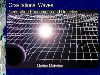
Einstein’s warpage of spacetime Imagine space as a stretched rubber sheet. A mass on the surface will cause a deformation. Another mass dropped onto the sheet will roll toward that mass. Einstein theorized that smaller masses travel toward larger masses, not because they are "attracted" by a mysterious force, but because the smaller objects travel through space that is warped by the larger object.
Predict the bending of light passing in the vicinity of the massive objects First observed during the solar eclipse of 1919 by Sir Arthur Eddington, when the Sun was silhouetted against the Hyades star cluster Their measurements showed that the light from these stars was bent as it grazed the Sun, by the exact amount of Einstein's predictions. The light never changes course, but merely follows the curvature of space. Astronomers now refer to this displacement of light as gravitational lensing.
Einstein’s Theory of Gravitation experimental tests “Einstein Cross” The bending of light rays gravitational lensing Quasar image appears around the central glow formed by nearby galaxy. The Einstein Cross is only visible in southern hemisphere. In modern astronomy, such gravitational lensing images are used to detect a ‘dark matter’ body as the central object
Einstein’s Theory of Gravitation experimental tests Mercury’s orbit perihelion shifts forward twice Newton’s theory Mercury's elliptical path around the Sun shifts slightly with each orbit such that its closest point to the Sun (or "perihelion") shifts forward with each pass. Astronomers had been aware for two centuries of a small flaw in the orbit, as predicted by Newton's laws. Einstein's predictions exactly matched the observation.
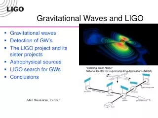
Einstein’s Theory of Gravitation gravitational waves • a necessary consequence of Special Relativity with its finite speed for information transfer • Einstein in 1916 and 1918put forward the formulation of gravitational waves in General Relativity • time dependent gravitational fields come from the acceleration of masses and propagate away from their sources as a space-time warpage at the speed of light gravitational radiation binary inspiral of compact objects
Einstein’s Theory of Gravitation gravitational waves • Using Minkowski metric, the information about space-time curvature is contained in the metric as an added term, hmn. In the weak field limit, the equation can be described with linear equations. If the choice of gauge is the transverse traceless gauge the formulation becomes a familiar wave equation • The strain hmn takes the form of a plane wave propagating with the speed of light (c). • Since gravity is spin 2, the waves have two components, but rotated by 450 instead of 900 from each other.
Gravitational Waves the evidence Neutron Binary System PSR 1913 + 16 -- Timing of pulsars 17 / sec · · ~ 8 hr
Hulse and Taylorresults emission of gravitational waves • due to loss of orbital energy • period speeds up 25 sec from 1975-98 • measured to ~50 msec accuracy • deviation grows quadratically with time
Radiation of Gravitational Waves Radiation of gravitational waves from binary inspiral system LISA • the center of the triangle formation will be in the ecliptic plane • 1 AU from the Sun and 20 degrees behind the Earth.
Astrophysics Sourcesfrequency range Audio band • EM waves are studied over ~20 orders of magnitude • (ULF radio -> HE rays) • Gravitational Waves over ~10 orders of magnitude • (terrestrial + space)
Interferometers terrestrial Suspended mass Michelson-type interferometers on earth’s surface detect distant astrophysical sources International network (LIGO, Virgo, GEO, TAMA) enable locating sources and decomposing polarization of gravitational waves.
Detection of Gravitational Waves interferometry Michelson Interferometer Fabry-Perot Arm Cavities suspended test masses LIGO (4 km), stretch (squash) = 10-18 m will be detected at frequencies of 10 Hz to 104 Hz. It can detect waves from a distance of 600 106 light years
Detection of Gravitational Waves interferometry – folded arms Folded arms – long light paths Schemes - delay line is simple but requires large mirrors - power recycling mirrors small, but harder controls problems t ~ 3 msec
Detection of Gravitational Waves interferometry – folded arms Power recycled Michelson Interferometer with Fabry-Perot arms • arm cavities store light for ~ 100 round trips or ~ 3 msec • power recycling re-uses light heading back to the laser giving an additional factor of x30
LIGO Interferometers end test mass Power Recycled Michelson Interferometer with Fabry-Perot Arm Cavities 4 km (2 km) Fabry-Perotarm cavity recycling mirror input test mass Laser beam splitter signal
LIGO Ithe noise floor • Interferometry is limited by three fundamental noise sources • seismic noise at the lowest frequencies • thermal noise at intermediate frequencies • shot noise at high frequencies • Many other noise sources lurk underneath and must be controlled as the instrument is improved
Noise Floor40 m prototype sensitivity demonstration • displacement sensitivity • in 40 m prototype. • comparison to predicted contributions from various noise sources
Phase Noisesplitting the fringe expected signal 10-10 radians phase shift demonstration experiment • spectral sensitivity of MIT phase noise interferometer • above 500 Hz shot noise limited near LIGO I goal • additional features are from 60 Hz powerline harmonics, wire resonances (600 Hz), mount resonances, etc
LIGO I interferometer • LIGO I configuration • Science Run 2002 -
LIGO Ithe noise floor • Interferometry is limited by three fundamental noise sources • seismic noise at the lowest frequencies • thermal noise at intermediate frequencies • shot noise at high frequencies • Many other noise sources lurk underneath and must be controlled as the instrument is improved
LIGOastrophysical sources LIGO I (2002-2005) LIGO II (2007- ) Advanced LIGO
Interferometersinternational network Simultaneously detect signal (within msec) Virgo GEO LIGO TAMA detection confidence locate the sources decompose the polarization of gravitational waves AIGO
LIGO Sites Hanford Observatory Livingston Observatory
LIGO Plansschedule 1996 Construction Underway (mostly civil) 1997 Facility Construction (vacuum system) 1998 Interferometer Construction (complete facilities) 1999 Construction Complete (interferometers in vacuum) 2000 Detector Installation (commissioning subsystems) 2001 Commission Interferometers (first coincidences) 2002 Sensitivity studies (initiate LIGOI Science Run) 2003+ LIGO I data run (one year integrated data at h ~ 10-21) 2005 Begin LIGO II installation
LIGO Facilitiesbeam tube enclosure • minimal enclosure • reinforced concrete • no services
LIGObeam tube • LIGO beam tube under construction in January 1998 • 65 ft spiral welded sections • girth welded in portable clean room in the field 1.2 m diameter - 3mm stainless 50 km of weld NO LEAKS !!
Beam Tube bakeout • I = 2000 amps for ~ 1 week • no leaks !! • final vacuum at level where not limiting noise, even for future detectors
LIGO I the noise floor • Interferometry is limited by three fundamental noise sources • seismic noise at the lowest frequencies • thermal noise at intermediate frequencies • shot noise at high frequencies • Many other noise sources lurk underneath and must be controlled as the instrument is improved
Vacuum Chambersvibration isolation systems • Reduce in-band seismic motion by 4 - 6 orders of magnitude • Compensate for microseism at 0.15 Hz by a factor of ten • Compensate (partially) for Earth tides
damped springcross section Seismic Isolationsprings and masses
102 100 10-2 10-6 Horizontal 10-4 10-6 10-8 Vertical 10-10 Seismic Isolationperformance HAM stack in air BSC stackin vacuum
Seismic Isolationsuspension system suspension assembly for a core optic • support structure is welded tubular stainless steel • suspension wire is 0.31 mm diameter steel music wire • fundamental violin mode frequency of 340 Hz
LIGO Noise Curvesmodeled wire resonances
Surface uniformity < 1 nm rms Scatter < 50 ppm Absorption < 2 ppm ROC matched < 3% Internal mode Q’s > 2 x 10⁶ Core Opticsfused silica Caltech data CSIRO data
LIGO laser • Nd:YAG • 1.064 mm • Output power > 8W in TEM00 mode
Deliver pre-stabilized laser light to the 15-m mode cleaner Frequency fluctuations In-band power fluctuations Power fluctuations at 25 MHz Tidal Wideband 4 km 15m 10-Watt Laser Interferometer PSL IO Laserstabilization • Provide actuator inputs for further stabilization • Wideband • Tidal 10-1 Hz/Hz1/2 10-4 Hz/ Hz1/2 10-7 Hz/ Hz1/2
Prestabalized Laserperformance • > 18,000 hours continuous operation • Frequency and lock very robust • TEM00 power > 8 watts • Non-TEM00 power < 10%
Commissioning configurations • Mode cleaner and Pre-Stabilized Laser • 2km one-arm cavity • short Michelson interferometer studies • Lock entire Michelson Fabry-Perot interferometer “FIRST LOCK”
Detector Commissioning: 2-km arm test • 12/99 – 3/00 • Alignment “dead reckoning” worked • Digital controls, networks, and software all worked • Exercised fast analog laser frequency control • Verified that core optics meet specs • Long-term drifts consistent with earth tides
Initial Alignmentconfirmation • Opening gate valves revealed alignment “dead reckoned” from corner station was within 100 micro radians beamspot
12/1/99 Flashes of light 12/9/99 0.2 seconds lock 1/14/00 2 seconds lock 1/19/00 60 seconds lock 1/21/00 5 minutes lock(on other arm) 2/12/00 18 minutes lock 3/4/00 90 minutes lock(temperature stabilized laser reference cavity) 3/26/00 10 hours lock Locking the Long Arm First interference fringes from the 2-km arm
Near-Michelson interferometer • power recycled (short) Michelson Interferometer • employs full mixed digital/analog servos Interference fringes from the power recycled near Michelsoninterferometer