Download
1 / 25
250 likes | 351 Views
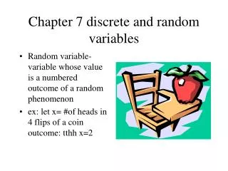
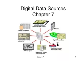
Chapter 7 Interfaces, Sources and Additional Variables. Introduction to CFX. Overview. Domain Interfaces are used for: Connection of mismatched meshes (hex to tet for example) The meshes may be in the same or different domains “Domain” in Domain Interfaces is a little misleading

E N D
Chapter 7Interfaces, Sources andAdditional Variables Introduction to CFX
Overview • Domain Interfaces are used for: • Connection of mismatched meshes (hex to tet for example) • The meshes may be in the same or different domains • “Domain” in Domain Interfaces is a little misleading • A single mesh file may contain non-matching mesh regions and require domain interfaces • Changes in reference frames between domains • Even if the mesh matches • Connect different types of domains together (e.g. Fluid to Solid) • Create periodic regions within a domain
Inserting Domain Interfaces • To create a domain interface right-click on the Flow Analysis or use the toolbar icon
Domain Interfaces and Boundary Objects • After creating a domain interface 3 new object are created in the outline tree • The interface object is at the Flow Analysis level • This is the object you should edit to make changes to the domain interface • Within each domain a Side 1 or Side 2 boundary condition is automatically created • In general do not edit these objects • They will be automatically updated when changes are made to the interface object The Side 1 and Side 2 boundary conditions The Interface object
Domain Interfaces Panel • Domain Interfaces connect two sets of surfaces together • Side 1 and Side 2 • First select the domain combination to be connected • Then select the Side 1 and Side 2 surface sets • The Domain (Filter) just limits the scope of the Region List to make selection easier • The Interface Models and Mesh Connection Method control how data is transferred across the interface What? How?
Interface Models • The available Interface Models are: • Translational Periodicity • Simulates geometries that have translational periodicity • Allows for either the mass flow rate or the pressure change across the interface to be specified • The quantity not specified will be part of the solution • Rotational Periodicity • Simulates rotationally periodic geometries • General Connection • For all other types of connections • A Frame Change/Mixing Model and a Pitch Change apply to rotating domain cases. These are discussed in the Moving Zones lecture
Mesh Connection Method • 1:1 • Only use this option if you are sure that the nodes on Side 1 and Side 2 of the interface match up exactly • Not recommended for Fluid – Solid and Solid – Solid interfaces • GGI • Use this option when the nodes on the two sides are not aligned • For best results both sides should have fairly similar mesh length scales • Fluxes are conserved across the interface • If the size of the connection region for one side is different to the other, the connection will be automatically made between the mutually overlapping surfaces (for best results ensure both sides fully overlap) • Possible to perform a connection where there is a “slight” gap or interference between the two sides of the GGI connection • The gap should be small relative to the mesh length scale • When solving, GGI connections use more memory and CPU than 1:1 connections
Mesh Connection Method • Automatic • This is generally the recommended option when available • In some cases only the GGI option will be available • It will try to make a 1:1 connection if possible, otherwise GGI • The Mesh Match Tolerance under Edit > Options > Mesh determines how close nodes need to be before a 1:1 connection can be made • The default value of 0.005 (0.5%) is a fraction of the local mesh length scale • In some situations a GGI connection will be used even when nodes match 1:1 • E.g. Fluid – Solid interfaces, since GGI connections are more accurate in these situations
Porous Interface Usage • Domain interfaces involving porous domains are always treated as GGI • Total Pressure is unchanged across the interface • Static pressure will show a discontinuity at the interface • Total Enthalpy (Total Energy) is unchanged across interface • May see a discontinuity in Enthalpy (Temperature) in high speed flows Total Pressure Velocity Static Pressure
Automatic Domain Interfaces • In some cases CFX-Pre will automatically create domain interfaces within a single mesh assembly if the mesh is from ANSYS Meshing: • To connect multiple domains and non-matching meshes within the assembly • Right-click on Mesh > View by > Region Typeto see a list of assemblies in the mesh • Always check the automatic interfaces to make sure they are appropriate! • You can disable automatic interface creation from Case Options > General in the Outline tree • You always need to manually create interfaces between mesh assemblies and when the mesh was not generated by ANSYS Meshing • However, a mesh with multiple assemblies but 1:1 node connections will usually be glued together to form 1 assembly, thus interfaces are not needed
Automatic Domain Interfaces CFX-Pre • The Connectivity entry in the Outline tree shows mesh connections that have been detected by CFX-Pre • You can right-click to add/remove connections • Automatic Domain Interface are created based on detected connections • Connections are created automatically & manually in the Meshing application in Workbench and passed to CFX-Pre • However, you must force all Meshing Connections to be 1:1 (i.e. 1 region connected to 1 region) for them to be successfully passed to CFX-Pre • In Meshing, select Connections from the Outlnie tree and set Group By = None Meshing
Energy Transport Equation Source Transient Convection Viscous work Conduction Source Terms • Sources add additional terms added to the solved transport equations • They provide a source (or sink) of the solved variable, e.g. • A source term added to the Energy Transport Equation represents a source of heat • A source / sink term added to the Momentum Equations represent adding / removing work to / from the system e.g. a pump / turbine • Source terms are often used as “black-boxes” • The details of the process producing the source are not simulated • E.g. instead of modelling a fan by resolving the blades and simulating the rotating motion, a source term is used to add momentum to the flow
3D, 2D & 1D Sources • Sources need to be applied at a 3D, 2D or 1D location • A sub domain is a 3D region within a domain that can be used to specify values for volumetric sources • Boundary sources permit the specification of sources as fluxes (source per unit area) on boundary condition surfaces • Source points are sources that act on a single mesh element Solid heater with Energy source term Dispersion of an Additional Variable from a Point Source
3D Sources – Subdomains • To add a Subdomain right-click on a Domain > Insert > Subdomain • A domain can contain many subdomains, if necessary • Subdomains cannot span multiple domains • Create separate subdomains for each domain • In Basic Settings the Location is specified • This can be any 3D mesh region in the domain, including the whole domain • When creating your geometry and mesh you should account for any regions where source terms are required • In general create a separate 3D solid in the geometry, then Form New Part in DM – gives a continuous mesh with distinct 3D regions
3D Sources – Subdomains • On the Sources tab a source term for each equation can be set • Momentum Sources have their own section on the Sources panel – see next slide • Sources may be constants or expressions • Sinks are just negative sources • The source Option can be: • Source: An amount per unit volume, e,g [W/m^3] • Total Source: The total amount applied to the subdomain, e.g. [W] • The optional Source Coefficient should be set (to improve convergence) if the source term is a function of the solved variable • E.g. an energy source which is a function of temperature • Set to the derivative of the source with respect to the solved variable
Momentum Sources can be set using a: General Momentum Source: similar to how sources are set for other equations Loss Model: when modeling porous materials, screens, etc it is easier to define the momentum source using a loss model This is based on Darcy’s Law, relating the pressure drop to the velocity through a Permeability and a Loss Coefficient or alternatively a Linear and Quadratic Resistance Coefficient 3D Sources – Momentum Sources Kperm= Permeability Coefficient Kloss= Loss Coefficient m /Kperm= Linear Resistance Coefficient Kloss r / 2 = Quadratic Resistance Coefficient • Pressure Drop due to the Permeability or Linear Resistance Coeff. scales with velocity • In Laminar flows pressure drop typically scales with velocity • Pressure Drop due to the Loss or Quadratic Resistance Coeff. scales with velocity2 • In Turbulent flows pressure drop typically scales with velocity2
2D sources are associated with boundary condition Each boundary condition has a Sources tab Settings are the same as 3D sources except either a Flux (source per unit area) is specified or a Total Source (total amount over the boundary) You cannot set Momentum sources on boundaries 2D Sources – Boundary Sources
1D Sources are created by right-clicking on the appropriate domain > Insert > Source Point, or using the toolbar icon 1D Sources – Source Points • Settings are similar to 3D sources except that you can only use the Total Source option • You cannot currently set a Momentum Source at a point • Source points are actually implemented as 3D sources on a single mesh element • Mesh refinement will refine the source point
Additional Variables Overview • Additional Variables (AV’s) are non-reacting scalar components that may be transported through the flow • They do not have any direct influence on the flow solution • You can set boundary conditions and sources for transported Additional Variables • Examples: • A tracer such as a dye or smoke • This is an example of a Transport Additional Variable. The AV is transported with the flow, but does not influence the flow • pH level • This is an example of an Algebraic Additional Variable. The AV is expressed as a function of other flow quantities through an algebraic expression, rather than solving a transport equation
AV’s are created by right-clicking on Expressions, Functions and Variables > Additional Variables, or using the toolbar icon Creating Additional Variables 1 • Variable Type • Specific: The AV is solved on a per-unit-mass basis • Volumetric: The AV is solved on a per-unit-volume basis • Unspecified: The AV is defined in terms of an algebraic expression • Units: the units that describe the additional variable • Tensor Type: Scalar or Vector as necessary
Creating Additional Variables • Once an AV has been created it must be included in the domain • Enable the AV on the domain > Fluid Models panel • Then boundary and initial values must be set (except Algebraic AV’s) 2 3
Domain Options • When including an AV in a domain the type of equation to solve is specified: • Transport Equation • A full transport equation is used • The transport of the AV occurs through both convection and diffusion • Setting the Kinematic Diffusivity controls laminar diffusion • Turbulent diffusion is always included Diffusion Advection Transient Sources
Domain Options • Diffusive Transport Equation • The advection term is dropped from the full transport equation – models a diffusion process • Poisson Equation • The advection and transient terms are dropped from the full transport equation • Has uses in electromagnetics Diffusion Sources Diffusion Transient Sources • Algebraic Equation / Vector Algebraic Equation • An expression (scalar) or three expression (vector) define the AV value throughout the domain
Tips • Additional Variables can be used to work-around some limitations: • You must pass a variable to the integrated CEL functions (areaAve(), voulmeInt(), etc). The following is not valid:areaAve(Velocity * Density)@Inletbecause Velocity * Density is an expression, not a variable • As a work-around you can create an Algebraic AV equal to the expressions, then pass in the AV to the CEL function • Creating an Additional Variable showing the age of the fluid in the domain is often useful for post-processing • This is done by creating a transport AV “Age” with units of [s] • Inlet and initial values should be zero • An AV source term with a value of 1 should be set throughout the domain
General Options • Under Case Options in the Outline tree Graphics Style and Labels and Markers control the Viewer look • General contains a number of useful options: • Automatic Default Domain and Automatic Default Interfaces: • Control the creation of these automatic objects • Automatic Physics Update: • By default CFX-Pre enforces all domains to use the same physics. In some cases you may want different physics in different domains. In general this is only valid when the domains are not directly connected, e.g. two fluid domains containing different fluids separated by a solid domain