Download
1 / 61
640 likes | 913 Views
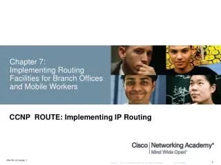
CCNP – Advanced Routing Ch. 6 - OSPF, Single Area – Part 2 of 3 Credits: this presentation was prepared by Rick Graziani Some modifications were made by Prof. Yousif.

E N D
CCNP – Advanced Routing Ch. 6 - OSPF, Single Area – Part 2 of 3 Credits: this presentation was preparedby Rick Graziani Some modifications were made by Prof. Yousif
For more information on OSPF, link-state routing protocol, Dijkstra’s algorithm and routing in general, check out these sources. Interconnections : Bridges and Routers by Radia Perlman Cisco IP Routing: Packet Forwarding & Intra-domain Routing Protocols by Alex Zinin This book has been especially helpful for information contained in these presentations. Routing TCP/IP Volume I by Jeff Doyle OSPF, Anatomy of an Internet Routing Protocol by John Moy (creator of OSPF)
Steps to OSPF Operation 1. Establishing router adjacencies 2. Electing DR and BDR 3. Discovering Routes 4. Choosing Routes 5. Maintaining Routing Information
OSPF States States of the OSPF neighbor FSM (Finite State Machine) • Every OSPF router represents its communications with other OSPF routers in the form of neighbor data structures. • Every neighbor can be in one of many states • Down State • Attempt State • Init State • Two-way State • ExStart State • Exchange State • Loading State • Full Adjacency State
Steps to OSPF Operation with OSPF States 1. Establishing router adjacencies • Down State • Init State • Two-way State • (ExStart State unless DR/BDR election needed) 2. Electing DR and BDR • ExStart State with DR and BDR • Two-way State with all other routers 3. Discovering Routes • ExStart State • Exchange State • Loading State • Full State 4. Choosing Routes 5. Maintaining Routing Information
1.Establishing Adjacencies • Initially, an OSPF router interface is in the down state. • An OSPF interface can transition back to this state if it has not received a Hello packet from a neighbor within the RouterDeadInterval time (40 seconds unless NBMA, 120 seconds). • In the down state, the OSPF process has not exchanged information with any neighbor. • OSPF is waiting to enter the init state. • An OSPF router tries to form an adjacency with at least one neighbor for each IP network it’s connected to.
1.Establishing Adjacencies • The process of establishing adjacencies is asymmetric, meaning the states between two adjacent routers may be different as they both transition to full state. • RTB perspective and assuming routers are configured correctly. • Trying to start a relationship and wanting to enter the init state or really the two-way-state • RTB begins multicasts OSPFHello packets (224.0.0.5, AllSPFRouters), advertising its own Router ID. • 224.0.0.5: All OSPF routers should be able to transmit and listen to this address.
1. Establishing Adjacencies • Router ID = Highest loopback address else highest active IP address. • Loopback address has the advantage of never going down, thus diminishing the possibility of having to re-establish adjacencies. (more in a moment) • Use private ip addresses for loopbacks, so you do not inadvertently advertise a route to a real network that does not exist on your router. • RTA and RTC receive Hello packets from RTB • RTA and RTC add RTB’s Router ID to the Neighbor ID field of the Hello packet its sends back to RTB, at the same time entering the init state.
1. Establishing Adjacencies Hello 10.6.0.1 10.5.0.1 Hello 10.6.0.1 2-way Down Init 2-way Down Init Init State • Init State - OSPF routers sent Type 1 Hello packets at regular intervals (10 sec.) to establish neighbors. • When a router receives its first Hello packet, it enters the init state, indicating that the Hello packet was received but did not contain the Router ID of the receiving router in the list of neighbors, so two-way communications is not yet ensured. • As soon as the router sends a Hello packet to the neighbor with its RouterID and the neighbor sends a Hello packet packet back with that Router ID, the router’s interface will transition to the two-way state. • Now, the router is ready to take the relationship to the next level. Hello 10.5.0.1 Hello 10.5.0.1 10.6.0.1
1. Establishing Adjacencies Hello 10.6.0.1 10.5.0.1 Hello 10.6.0.1 2-way Down Init 2-way Down Init From init state to the two-way state • RTB receives Hello packets from RTA and RTC (its neighbors), and sees its own Router ID (10.6.0.1) in the Neighbor ID field. • RTB declares takes the relationship to a new level, and declares a two-way state between itself and RTA, and itself and RTC. • As soon as the router sends a Hello packet to the neighbor with its RouterID and the neighbor sends a Hello packet packet back with that Router ID, the router’s interface will transition to the two-way state. • Now, the router is ready to take the relationship to the next level. Hello 10.5.0.1 Hello 10.5.0.1 10.6.0.1
1. Establishing Adjacencies Two-way state(and adjacency) • Using Type-1 Hello packets every OSPF router tries to establish a two-way state or bi-directional communication with every neighbor router on the same IP network. • Among other information, these Hello packets include a list of the sender’s known OSPF neighbors. • A router enters the two-way state when it sees itself in a neighbor’s Hello packet. • As we will see later, a router may stay in this state if it is on a broadcast segment and it is neither the DR or the BDR. (later) • To learn about other routers’ link states and eventually build a routing table, every OSPF router must form at least one “adjacency” and involve a series of progressions that will not just rely just on hellos, but the other four kinds of OSPF packets.
1. Establishing Adjacencies Two-way state • RTB now decides who to establish a “full adjacency” with depending upon the type of network that the particular interfaces resides on. • Note: The term adjacency is used to both describe routers reaching 2-way state and when they reach full-state. Not to go overboard on this, but technically OSPF routers are adjacent when the FSM reaches full-state and IS-IS is considered adjacent when the FSM reaches 2-way state. Two-way state to ExStart state • If the interface is on a point-to-point link, the routers becomes adjacent with its sole link partner (aka “soul mates”), and take the relationship to the next level by entering the ExStart state. (coming soon) Remaining in the two-way state • If the interface is on a multi-access link (Ethernet, Frame Relay, …) RTB must enter an election process to see who it will establish a full adjacency with, and remains in the two-way state. (Next!)
Steps to OSPF Operation with OSPF States 1. Establishing router adjacencies • Down State – No Hello received • Init State – Hello received, but not with this router’s Router ID • Two-way State – Hello received, and with this router’s Router ID • (ExStart State unless DR/BDR election needed) 2. Electing DR and BDR – Broadcast segments only • ExStart State with DR and BDR • Two-way State with all other routers 3. Discovering Routes • ExStart State • Exchange State • Loading State • Full State 4. Calculating the Routing Table 5. Maintaining the LSDB and Routing Table
2. Electing a DR and BDR • On point-to-point links adjacencies (don’t get this confused with being “fully adjacent” or the full state) are established with all neighbors, because there is only one neighbor. • On multi-access networks,OSPF elects a DR and BDR to limit the number of adjacencies using OSPF Hello packets. • Reduce routing update traffic
2. Electing a DR and BDR • DR - Designated Router • BDR – Backup Designated Router • DR’s serve as collection points for Link State Advertisements (LSAs) • A BDR back ups the DR. • If the IP network is multi-access, the OSPF routers will elect 1 DR and 1 BDR (unless there is only 1 router on the network).
2. Electing a DR and BDR • The formation of an adjacency between every attached router would create many unncessary LSA (Link State Advertisements), n(n-1)/2 adjacencies. • Flooding on the network itself would be chaotic. • A router would flood an LSA to all its adjacent neighbors, which in turn would flood it to all their adjacent neighbors, and so on, creating many copies of the same LSA on the same network. • To prevent this problem, a Designate Router (DR) is elected on multi-access networks. • Not knowing any different, at first all routers declare themselves the DR until it learns differently. • Technical Note: In reality the BDR selection process happens first to ensure the BDR takes over the DR responsibilities when the DR fails.
2. Electing a DR and BDR Designated Router • A DR (Designated Router) and perhaps a BDR (Backup Designated Router) is elected for every multi-access network, using Hello packets as “ballots.” • Router with the highest Router ID is elected the DR. • But like other elections, this one can be rigged. • The router’s priority field can be set to either ensure that it becomes the DR or prevent it from being the DR. Rtr(config-if)# ip ospf priority <0-255> • Higher priority becomes DR/BDR • Default = 1 • 0 = Ineligible to become DR/BDR • The router can be assigned a priority between 0 and 255, with 0 preventing this router from becoming the DR (or BDR) and 255 ensuring at least a tie. (The highest Router ID would break the tie.)
2. Electing a DR and BDR Backup Designated Router • BDR (Backup Designated Router) is elected in addition to the DR in case the DR fails. • The BDR is the router that wins second place in the previous process. • If a multi-access network only has one router, it will be the DR and there will be no BDR. • NOTE: On an multi-access stub network, there it becomes the DR and there is no BDR. When a second router is added to the segment, it will become the BDR, regardless of priority or router id.
2. Electing a DR and BDR • All other routers, “DRother”, establish adjacencies with only the DR and BDR. • DRother routers multicast LSAs to only the DR and BDR • (224.0.0.6 - all DR routers) • DR sends LSA to all adjacent neighbors • (224.0.0.5 - all OSPF routers) Backup Designated Router - BDR • Listens, but doesn’t act. • If LSA is sent, BDR sets a timer. • If timer expires before it sees the reply from the DR, it becomes the DR and takes over the update process. • The process for a new BDR begins. DRother Routers
2. Electing a DR and BDR A new router enters the network • Once a DR is established, a new router that enters the network with a higher priority or router id will NOT become the DR or BDR. (Bug in early IOS 12.0) • There is a valid condition where this may arise, but it is unlikely. (If a router enters a network and does not hear a hello from routers already on the network.) • If DR fails, BDR takes over as DR and selection process for new BDR begins. • State of the relationship • DROthers enter ExStart state with DR and BDR and two-way state with all other routers • DR and BDR enter ExStart state with all routers
2. Electing a DR and BDR DR - Summary DR Election • Router with the highest interface priority (0 = cannot become DR or BDR) • Router with the highest router ID. • Loopback address used first • IP Address on active interface used second • BDR is the second highest Adjacencies and multicasting • All other routers, DRother, establish adjacencies with only the DR and BDR. • All routers continue to multicast Hello packets to AllSPFRouters (224.0.0.5) so they can track neighbors. • But updates (LSAs) are multicast to DR and BDR only (224.0.0.6 - AllDRrouters) and in turn • DR floods updates (LSAs) to all adjacent neighbors (224.0.0.5 - AllSPFRrouters)
2. Electing a DR and BDR BDR • Listens, but doesn’t act. • If LSA is sent, BDR sets a timer. • If timer expires before it sees the reply from the DR, it becomes the DR and takes over the update process and the process for a new BDR begins.
2. Electing a DR and BDR Hello DR 10.6.0.1 ExStart 2-way ExStart 2-way DR and BDR get elected and FSM interface transitions from two-way state to the ExStart state Note: Any DROther routers remain in two-way state with each other, but ExStart state with DR and BDR. BDR DR Hello DR 10.5.0.1
Steps to OSPF Operation with OSPF States 1. Establishing router adjacencies • Down State – No Hello received • Init State – Hello received, but not with this router’s Router ID • Two-way State – Hello received, and with this router’s Router ID • (ExStart State unless DR/BDR election needed) 2. Electing DR and BDR – Broadcast segments only • ExStart State – Router interfaces with DR and BDR • Two-way State – Router interfaces with all other routers 3. Discovering Routes • ExStart State –Starts LSDB synchronization process between neighbors. Decide on Master/Slave. • Exchange State – Routers exchange DBD packets and determines if there is anything in its Link State Request list. • Loading State – If entries in LSR list, exchange LSUs. • Full State – Once LSDBs are synchronized. 4. Calculating the Routing Table 5. Maintaining the LSDB and Routing Table
3. Discovering Routes and reaching Full State “adjacent” OSPF Type-2 (DBD) OSPF Type-2 (DBD) OSPF Type-2 (DBD) OSPF Type-2 (DBD) OSPF Type-5 (LSAck) OSPF Type-3 (LSR) OSPF Type-4 (LSU) OSPF Type-5 (LSAck) “full adjacency”
3. Discovering Routes and reaching Full State ExStart State • This state starts the LSDB (Link State Data Base) synchronization process. • This will prepare for initial database exchange. • Routers are now ready to exchange routing information. • Between routers on a point-to-point network • On a multi-access network between the DRothers and the DR and BDR. • Formally, routers in ExStart state are characterized as adjacent, but have not yet become “fully adjacent” as they have not exchanged data base information. But who goes first in the exchange? • ExStart is established by exchanging OSPF Type-2 DBD (Database Description) packets (I believe the curriculum says LSA type 2 which is something else). • Purpose of ExStart is to establish a master/slave relationship between the two routers decided by the higher router id. • Once the roles are established they enter the Exchange state.
OSPF packet types OSPF Type-2 (DBD) OSPF Type-3 (LSR) OSPF Type-4 (LSU) OSPF Type-5 (LSAck)
OSPF DBD packet format 0 1 2 3 0 1 2 3 4 5 6 7 8 9 0 1 2 3 4 5 6 7 8 9 0 1 2 3 4 5 6 7 8 9 0 1 +-+-+-+-+-+-+-+-+-+-+-+-+-+-+-+-+-+-+-+-+-+-+-+-+-+-+-+-+-+-+-+-+ | Version # | 2 | Packet length | +-+-+-+-+-+-+-+-+-+-+-+-+-+-+-+-+-+-+-+-+-+-+-+-+-+-+-+-+-+-+-+-+ | Router ID | +-+-+-+-+-+-+-+-+-+-+-+-+-+-+-+-+-+-+-+-+-+-+-+-+-+-+-+-+-+-+-+-+ | Area ID | +-+-+-+-+-+-+-+-+-+-+-+-+-+-+-+-+-+-+-+-+-+-+-+-+-+-+-+-+-+-+-+-+ | Checksum | AuthType | +-+-+-+-+-+-+-+-+-+-+-+-+-+-+-+-+-+-+-+-+-+-+-+-+-+-+-+-+-+-+-+-+ | Authentication | +-+-+-+-+-+-+-+-+-+-+-+-+-+-+-+-+-+-+-+-+-+-+-+-+-+-+-+-+-+-+-+-+ | Authentication | +-+-+-+-+-+-+-+-+-+-+-+-+-+-+-+-+-+-+-+-+-+-+-+-+-+-+-+-+-+-+-+-+ | Interface MTU | Options |0|0|0|0|R|I|M|MS +-+-+-+-+-+-+-+-+-+-+-+-+-+-+-+-+-+-+-+-+-+-+-+-+-+-+-+-+-+-+-+-+ | DD sequence number | +-+-+-+-+-+-+-+-+-+-+-+-+-+-+-+-+-+-+-+-+-+-+-+-+-+-+-+-+-+-+-+-+ | | +- -+ | | +- An LSA Header -+ | | +- -+ | | +- -+ | | +-+-+-+-+-+-+-+-+-+-+-+-+-+-+-+-+-+-+-+-+-+-+-+-+-+-+-+-+-+-+-+-+ | ... | (LSA descriptions)
3. Discovering Routes and reaching Full State “adjacent” OSPF Type-2 (DBD) OSPF Type-2 (DBD) OSPF Type-2 (DBD) OSPF Type-2 (DBD) OSPF Type-5 (LSAck) OSPF Type-3 (LSR) OSPF Type-4 (LSU) OSPF Type-5 (LSAck)
3. Discovering Routes and reaching Full State Exchange State • Exchange state - Routers exchange one or more Type-2 DBDs (Database Description) packets, which is a summary of the link-state database • send LSAcks to verify • Routers compare these DBDs with information in its own database. • When a DBD packet is received the router looks through the LSA (Link State Advertisement) headers and identifies LSAs that are not in the router’s LSDB or are a different version from its LSDB version (older or newer). • If the LSA is not in its LSDB or the LSA is a more recent version, the router adds an entry to its Link State Request list. • This process ends when both routers stop have sent and received acknowledgements for all their DBD packets – that is they have successfully sent all their DBD packets to each other.
3. Discovering Routes and reaching Full State Exchange State • If a router has entries in its Link State Request list, meaning that it needs additional information from the other router for routes that are not in its LSDB or has more recent versions, then it enters the loading state. • If there are no entries in its Link State Request list, than the router’s interface can transition directly to full state. • Complete routing information is exchanged in the loading state, discussed next.
3. Discovering Routes and reaching Full State “adjacent” OSPF Type-2 (DBD) OSPF Type-2 (DBD) OSPF Type-2 (DBD) OSPF Type-2 (DBD) OSPF Type-5 (LSAck) OSPF Type-3 (LSR) OSPF Type-4 (LSU) OSPF Type-5 (LSAck)
3. Discovering Routes and reaching Full State Loading State • If a router has entries in its Link State Request list, meaning that it needs additional information from the other router for routes that are not in its LSDB or has more recent versions, then it enters the loading state. • The router needing additional information sends LSR (Link State Request) packets using LSA information from its LSR list. OSPF packet types OSPF Type-2 (DBD) OSPF Type-3 (LSR) OSPF Type-4 (LSU) OSPF Type-5 (LSAck)
OSPF LSR packet format 0 1 2 3 0 1 2 3 4 5 6 7 8 9 0 1 2 3 4 5 6 7 8 9 0 1 2 3 4 5 6 7 8 9 0 1 +-+-+-+-+-+-+-+-+-+-+-+-+-+-+-+-+-+-+-+-+-+-+-+-+-+-+-+-+-+-+-+-+ | Version # | 3 | Packet length | +-+-+-+-+-+-+-+-+-+-+-+-+-+-+-+-+-+-+-+-+-+-+-+-+-+-+-+-+-+-+-+-+ | Router ID | +-+-+-+-+-+-+-+-+-+-+-+-+-+-+-+-+-+-+-+-+-+-+-+-+-+-+-+-+-+-+-+-+ | Area ID | +-+-+-+-+-+-+-+-+-+-+-+-+-+-+-+-+-+-+-+-+-+-+-+-+-+-+-+-+-+-+-+-+ | Checksum | AuType | +-+-+-+-+-+-+-+-+-+-+-+-+-+-+-+-+-+-+-+-+-+-+-+-+-+-+-+-+-+-+-+-+ | Authentication | +-+-+-+-+-+-+-+-+-+-+-+-+-+-+-+-+-+-+-+-+-+-+-+-+-+-+-+-+-+-+-+-+ | Authentication | +-+-+-+-+-+-+-+-+-+-+-+-+-+-+-+-+-+-+-+-+-+-+-+-+-+-+-+-+-+-+-+-+ | LS type | +-+-+-+-+-+-+-+-+-+-+-+-+-+-+-+-+-+-+-+-+-+-+-+-+-+-+-+-+-+-+-+-+ | Link State ID | +-+-+-+-+-+-+-+-+-+-+-+-+-+-+-+-+-+-+-+-+-+-+-+-+-+-+-+-+-+-+-+-+ | Advertising Router | +-+-+-+-+-+-+-+-+-+-+-+-+-+-+-+-+-+-+-+-+-+-+-+-+-+-+-+-+-+-+-+-+ | ...| LSR (LSRs)
3. Discovering Routes and reaching Full State Loading State • The other routers replies by sending the requested LSAs in the Link State Update (LSU) packet. • The receiving router sends LSAck to acknowledge receipt. • When all LSAs on the neighbors Link State Request list have been received, the “neighbor FSM” transitions this interface to Full state. OSPF packet types OSPF Type-2 (DBD) OSPF Type-3 (LSR) OSPF Type-4 (LSU) OSPF Type-5 (LSAck)
OSPF LSU packet format 0 1 2 3 0 1 2 3 4 5 6 7 8 9 0 1 2 3 4 5 6 7 8 9 0 1 2 3 4 5 6 7 8 9 0 1 +-+-+-+-+-+-+-+-+-+-+-+-+-+-+-+-+-+-+-+-+-+-+-+-+-+-+-+-+-+-+-+-+ | Version # | 4 | Packet length | +-+-+-+-+-+-+-+-+-+-+-+-+-+-+-+-+-+-+-+-+-+-+-+-+-+-+-+-+-+-+-+-+ | Router ID | +-+-+-+-+-+-+-+-+-+-+-+-+-+-+-+-+-+-+-+-+-+-+-+-+-+-+-+-+-+-+-+-+ | Area ID | +-+-+-+-+-+-+-+-+-+-+-+-+-+-+-+-+-+-+-+-+-+-+-+-+-+-+-+-+-+-+-+-+ | Checksum | AuType | +-+-+-+-+-+-+-+-+-+-+-+-+-+-+-+-+-+-+-+-+-+-+-+-+-+-+-+-+-+-+-+-+ | Authentication | +-+-+-+-+-+-+-+-+-+-+-+-+-+-+-+-+-+-+-+-+-+-+-+-+-+-+-+-+-+-+-+-+ | Authentication | +-+-+-+-+-+-+-+-+-+-+-+-+-+-+-+-+-+-+-+-+-+-+-+-+-+-+-+-+-+-+-+-+ | # LSAs | +-+-+-+-+-+-+-+-+-+-+-+-+-+-+-+-+-+-+-+-+-+-+-+-+-+-+-+-+-+-+-+-+ | | +- +-+ | LSAs | +- +-+ | ... | LSAs: Types 1, 2, 3, 4, or 5 LSAs
OSPF packet types – More later OSPF Type-4 packets have 7 LSA packets (later)
3. Discovering Routes and reaching Full State Full State • Full state - after all LSRs have been updated. • At this point the routers should have identical LSDBs (link-state databases). Flooding LSAs • Once this interface transitions to or from Full state the router originates a new version of a Router LSA (LSA Type –1, coming) and floods it to its neighbors, distributing the new topological information – out all OSPF enabled interfaces. • Broadcast networks: • DR: If the LSA was received on this interface, send it out this interface so DROthers receive it (224.0.0.5 - all OSPF routers) • BDR/DROther: If the LSA was received on this interface, do not send out this interface (received from DR). Calculating Routing Table • The router still must calculate its routing table – Next!
3. Discovering Routes and reaching Full State “adjacent” OSPF Type-2 (DBD) OSPF Type-2 (DBD) OSPF Type-2 (DBD) OSPF Type-2 (DBD) OSPF Type-5 (LSAck) OSPF Type-3 (LSR) OSPF Type-4 (LSU) OSPF Type-5 (LSAck)
Steps to OSPF Operation with OSPF States 1. Establishing router adjacencies • Down State – No Hello received • Init State – Hello received, but not with this router’s Router ID • Two-way State – Hello received, and with this router’s Router ID • (ExStart State unless DR/BDR election needed) 2. Electing DR and BDR – Broadcast segments only • ExStart State – Router interfaces with DR and BDR • Two-way State – Router interfaces with all other routers 3. Discovering Routes • ExStart State • Exchange State • Loading State • Full State 4. Calculating the Routing Table 5. Maintaining the LSDB and Routing Table
4. Calculating the Routing Table • The router now has a complete link-state database • Now the router is ready to create a routing table, but first needs to run the Shortest Path First Algorithm on the link state database, which will create the SPF tree. • Dijkstra’s algorithm is used to calculate the Shortest Path Tree from the LSAs in the link state database. • SPF, Shortest Path First calculations places itself as the root and creating a “tree diagram” of the network.
4. Calculating the Routing Table • The LSAs that build the database contain three important pieces of generic information: RouterID of the sender of the LSA, the NeighborID, and cost of the link between the Router and the neighbor (I.e the state of the link or link-state). • We will not go into the details here, but the books mentioned earlier all some excellent examples on this process. • Also, remember the link-state exercise we did earlier! Exercise: From link-state flooding to routing tables + =
4. Calculating the Routing Table Cost = 108/BW • OSPF basis routing metrics on cost. • Cisco routers, cost = 108/BW • Note for both IGRP and EIGRP it is 107, whereas OSPF is 108 • BW is the configured bandwidth for an interface (See CCNA IGRP information) • Cisco uses a default cost of 108/BW, where BW is the configured bandwidth (bandwidth command) of the interface and 108 (100,000,000) as the reference bandwidth. • Example: A serial link with a configured bandwidth of 128K would have a cost of: 100,000,000/128,000 = 781 • The cost of a route is the sum of the costs of all the outgoing interfaces to a destination. • In general, cost decreases as the speed of the link increases. • RTB’s 10 Mbps Ethernet interface has a lower cost than its T-1, 1.544 Mbps interface.
4. Calculating the Routing Table Cisco default interface costs: • 56-kbps serial link—Default cost is 1785 • 64-kbps serial link—Default cost is 1562 • T1 (1.544-Mbps serial link)—Default cost is 65 • E1 (2.048-Mbps serial link)—Default cost is 48 • 4-Mbps Token Ring—Default cost is 25 • Ethernet—Default cost is 10 • 16-Mbps Token Ring—Default cost is 6 • FDDI—Default cost is 1 Notes: • Cisco routers default to T1 (1.544 Mbps) on all serial interfaces and require manual modification with the bandwidth command. • ospf auto-cost reference-bandwidthref-bw can be used to modify the reference-bandwidth for higher speed interfaces
4. Calculating the Routing Table Modifying the cost • bandwidth command can be used to change the bandwidth metric on an interface and used in the 108/BW calculation: RTB(config)# inter s 0 RTB(config-if)# bandwidth 56 (in Kbps) Note: The metric for this interface is now 1785. • ip ospf cost is used when converting the metric between routers from different vendors. It overrides the default cost and becomes the metric for that interface. Bay Networks and some other vendors use a default cost of 1 on all interfaces, essentially making the OSPF cost reflect hop counts. RTB(config)# inter s 0 RTB(config-if)# ip ospf cost 1000 Note: The metric for this interface is now 1000. Note: For the Cisco IOS cost formula to be accurate it is important to have appropriate costs on both sides of a link.
4. Calculating the Routing Table • In the next chapter we will discuss OSPF and multiple areas. • Here is some information regarding the routing table calculation that we will discuss again in the chapter on OSPF multiple areas: • OSPF areas are designed to keep issues like flapping links within an area. • SPF is not recalculated if the topology change is in another area. • The interesting thing is that OSPF distributes inter-area (between areas) topology information using a distance-vector method. • OSPF uses link-state principles only within an area. • ABRs relay routing information between areas via distance vector technique similar to RIP or IGRP.
4. Calculating the Routing Table FYI: The rest of the story, which will be discussed in OSPF multiple areas. OSPF areas are designed to keep issues like flapping links within an area. SPF is not recalculated if the topology change is in another area. The interesting thing is that OSPF distributes inter-area (between areas) topology information using a distance-vector method. OSPF uses link-state principles only within an area. ABRs do not announce topological information between areas, instead, only routing information is injected into other areas. ABRs relay routing information between areas via distance vector technique similar to RIP or IGRP. This is why show ip ospf does not show a change in the number of times SPF has been executed when the topology change is in another area. Note: It is still a good idea to perform route summarization between areas, announcing multiple routes as a single inter-area route. This will hide any changes in one area from affecting routing tables in other areas.For more information, look at Cisco IP Routing by Alex Zinin.
4. Calculating the Routing Table SPF Holdtime • SPF algorithm is CPU intensive and takes some time depending upon the size of the area (coming next week), the number of routers, the size of the link state database. • A flapping link can cause an OSPF router to keep on recomputing a new routing table, and never converge. • To minimize this problem: • SPF calculations are delayed by 5 seconds after receiving an LSU (Link State Update) • Delay between consecutive SPF calculations is 10 seconds • You can configure the delay time between when OSPF receives a topology change and when it starts a shortest path first (SPF) calculation (spf-delay). • You can also configure the hold time between two consecutive SPF calculations (spf-holdtime). Router(config-router)#timersspf spf-delay spf-holdtime
4. Calculating the Routing Table RTB#show ip ospf 1 Routing Process "ospf 1" with ID 10.6.0.1 <OUTPUT OMITTED> Area BACKBONE(0) Number of interfaces in this area is 2 Area has no authentication SPF algorithm executed 5 times Area ranges are Number of LSA 4. Checksum Sum 0x1D81A Number of opaque link LSA 0. Checksum Sum 0x0 Number of DCbitless LSA 0 Number of indication LSA 0 Number of DoNotAge LSA 0 Flood list length 0
5.Maintaining the LSDB and the Routing Table Routes are kept in the IP routing table (show ip route) • Note: There is a routing table which is internal to the OSPF process. This internal routing table contains information used as an intermediate result for inter-area and external route calculations and contains routes to ABRs and ASBRs. (Just a technical note and fyi.) RouterA#show ip route Codes: I - IGRP derived, R - RIP derived, O - OSPF derived, C - connected, S - static, E - EGP derived, B - BGP derived, * - candidate default route, IA - OSPF inter area route, i - IS-IS derived, U - per-user static route, o - on-demand routing, D - EIGRP, EX - EIGRP external, E1 - OSPF external type 1 route, E2 - OSPF external type 2 route, N1 - OSPF NSSA external type 1 route, N2 - OSPF NSSA external type 2 route 2.0.0.0/8 is subnetted, 1 subnets C 2.2.202.0 is directly connected, Loopback0 O IA 206.202.0.0/24 [110/84] via 206.202.2.1, 00:10:45, Ethernet0 O 206.202.1.0/24 [110/74] via 206.202.2.1, 00:10:46, Ethernet0 C 206.202.2.0/24 is directly connected, Ethernet0 O E2 10.0.0.0/8 [110/500] via 206.202.2.1, 00:10:46, Ethernet0 O E2 162.10.0.0/16 [110/500] via 206.202.2.1, 00:10:46, Ethernet0 O IA 192.10.10.0/24 [110/148] via 206.202.2.1, 00:10:46, Ethernet0 O IA 192.10.5.0/24 [110/158] via 206.202.2.1, 00:10:46, Ethernet0