NT-8-Single Carrier PHY
NT-8-Single Carrier PHY. Date: 2010-05-16. Proposal overview. This presentation is part and in support of the complete proposal described in 802.11-10/432r0 (slides) and 802.11-10/433r0 (text) that: Supports data transmission rates up to 7 Gbps

NT-8-Single Carrier PHY
E N D
Presentation Transcript
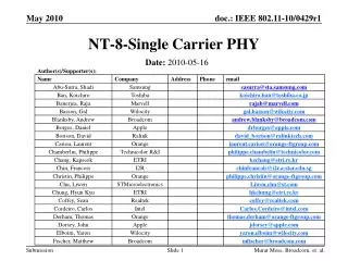
NT-8-Single Carrier PHY Date: 2010-05-16 Murat Mese, Broadcom, et. al.
Proposal overview • This presentation is part and in support of the complete proposal described in 802.11-10/432r0 (slides) and 802.11-10/433r0 (text) that: • Supports data transmission rates up to 7 Gbps • Supplements and extends the 802.11 MAC and is backward compatible with the IEEE 802.11 standard • Enables both the low power and the high performance devices, guaranteeing interoperability and communication at gigabit rates • Supports beamforming, enabling robust communication at distances beyond 10 meters • Supports GCMP security and advanced power management • Supports coexistence with other 60GHz systems • Supports fast session transfer among 2.4GHz, 5GHz and 60GHz Murat Mese, Broadcom, et. al.
Overview 1 • Proposed: Three different MCSs • SC MCS with low-PAPR encoding • OFDM MCS • Control MCS • SC MCS and OFDM MCS share the same preamble structure. • Control MCS for beacons and beamforming initialization with differential BPSK • Common FEC is used for all MCSs. Murat Mese, Broadcom, et. al.
Overview 2: Channelization • Channelization is identical to IEEE 802.15.3c. • Channel bandwidth is 2160 MHz with the following 4 center frequencies defined: 58.32, 60.48, 62.64, and 64.8 GHz. Murat Mese, Broadcom, et. al.
Overview 3: Spectral Mask (All Modes) 0 dBr -20 dBr -25 dBr -30 dBr -2.2 -1.6 -1.1 -0.94 0 +0.94 +1.1 +1.6 +2.2 (f-fc) (GHz) Murat Mese, Broadcom, et. al.
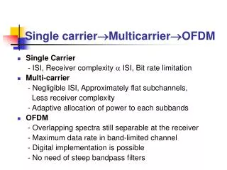
Overview 4: SC and OFDM • Single Carrier (SC) vs. OFDM • In favor of OFDM • Lower-complexity receiver implementation for long multipath channels • In favor of single carrier • Low PAPR, efficient PA, lower transmitter complexity and power consumption • Somewhat better FER vs. input SNR at higher code rates • Dual-Mode PHY is a good solution: • SC MCSs mainly targeted toward hand-held and other energy- and/or power-constrained devices. • Digital still and video cameras are good examples (transmitter-dominant). • OFDM MCSs mainly targeted toward high-throughput applications. Refer to [2] for OFDM MCS discussion. • SC MCS and OFDM MCS rates are defined in different MCSs in the same MCS table (starting from MCS1). • A low-rate “Control MCS ” (MCS 0) is necessary in both SC and OFDM devices for beamformer initialization and for beacons (next slide). May 2010 Slide 10 Murat Mese, Broadcom, et. al.
Overview 5: Control MCS • Beamforming is necessary in 60GHz systems, and Control MCS (MCS 0) is required for SC or SC/OFDM Dual-Mode devices to communicate with each other before setting up beamforming connections. • Main usage of Control MCS: • Beacons • Beamforming training. • Control MCS Design Aspects: • SNR sensitivity (or effective rate) targeted for ~15dB lower than the sensitivity point of 1Gbps data rate • Uses SC with spreading to achieve a much lower rate. May 2010 Slide 11 Murat Mese, Broadcom, et. al.
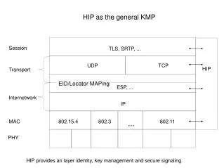
Overview 6: Common Preamble • Preamble is the beginning part of a PPDU—used for packet detection, AGC, frequency/timing synchronization, channel estimation, and signaling of PSDU modulation (SC MCS /OFDM MCS /Control MCS). • Regular SC and OFDM MCSs share a common preamble: • Better support of the coexistence between various types of devices • Each device (especially Dual-Mode device) need implement only one packet detection/synchronization/channel estimation mechanism. • Appropriate auto-detection and re-sampling mechanism are required. • Given that OFDM and SC Data portion uses different sample/symbol rates. • Control MCS applies a longer preamble with similar design to SC/OFDM: • For operation at lower input SNR (greater path loss) • Appropriate auto-detection between Control MCS and regular SC/OFDM MCS preambles is needed. Refer to [1] for common preamble discussion. May 2010 Slide 12 Murat Mese, Broadcom, et. al.
Overview 7: Common FEC • FEC selected is a fixed-block length LDPC code. • 672 bits to enable low-power decoding techniques. • Each of the four code rates can be derived from a template (enabling smaller, lower-power decoders). • Codes support efficient implementation of layer and fully parallel belief propagation decoders. • PPDU encoding is very simple. • Only shortening is used, no puncturing. May 2010 Slide 13 Murat Mese, Broadcom, et. al.
SC MCS Frame Format • Definitions: • STF: Short Training Field (acquisition) • CEF: Channel Estimation Field • BLK: data block (described in payload encoding) • Optional trailing AGC subfields and TRN-R/T subfields are for beamforming and not described further in this document. • Refer to [3] for details. STF CEF Header BLK BLK … BLK AGC TRN-R/T Murat Mese, Broadcom, et. al.
MCS Table for Single-carrier (SC) MCS and Control MCS Control MCS SC MCS symbol (chip) rate is 1760 Msym/sec. OFDM sample rate is 2640 (= 3/2 * 1760) Msamples/sec. Murat Mese, Broadcom, et. al.
Modulation: pi/2-BPSK (1) • p/2-BPSK is simply BPSK encoded with a p/2 phase rotation on every successive symbol: sout,k = sin,k * ei*p/2*k, where i = sqrt(-1) and k = 0,1, … is the symbol index. • Two phase transitions are possible with every symbol for BPSK, but 4 constellation points are used. • Refer to [4] for use of same rotation scheme. • p/2-BPSK with appropriate filtering can be used to approximate a precoded Gaussian Minimum-Shift Keying (GMSK), which is a constant-envelope modulation. • Vs. OFDM, a 5-dB reduction in output back-off (OBO) is possible. • Excellent for antenna-constrained hand-held devices Murat Mese, Broadcom, et. al.
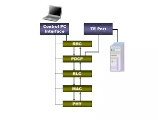
BPSK Mapper p/2 Chip Rotator Quadrature Modulator LPF Bits in (G)MSK Modulator Bits in Option 1: p/2-BPSK Realization + D Modulation: pi/2-BPSK (2) • p/2 rotation continues throughout the entire SC frame (including payload), regardless of payload constellation. Option 2: Equivalent Precoded (G)MSK Realization Murat Mese, Broadcom, et. al.
SC MCS Symbol Block Format GI DATA GI DATA GI DATA GI • Two 672-bit LDPC codewords fit exactly into 3 blocks of data for p/2-BPSK. • Shortening performed only at end of frame • Simplifies receiver • GI is a fixed L=64 Golay sequence. • Not a cyclic prefix, though blocks still have a cyclic property if the GI of the next symbol is included. • Useful for parameter updates and enables either time- or frequency-domain equalization • Control MCS does not use symbol blocking with GI. 64 448 symbols 64 448 symbols 64 448 symbols 64 Trailing GI to maintain cyclic property for last symbol block. Murat Mese, Broadcom, et. al.
SC MCS Payload Encoding • Payload bits are broken into blocks of LCWD = 336, 420, 504, or 545 data bits and encoded by the LDPC codeword encoder to produce blocks of 672 bits. • Data pad (0) is added to ensure that full codewords are transmitted. • The zero bits are scrambled with the continuation of the scrambler sequence. • Block pad (0) is added to ensure that full SC blocks are transmitted. • The zero bits are scrambled with the continuation of the scrambler sequence. • An inner repetition code (with scrambler to reduce spectral lines in the output) is applied for MCS1. • Up to 168 bits are encoded per codeword (with 336 parity bits). Murat Mese, Broadcom, et. al.
Common LDPC Code Set • Code rates: R1=1/2, R2=5/8, R3=3/4 and R4=13/16, all 672 bits • Each of the parity-check matrices H is partitioned into square sub-matrices of size Z x Z. The sub-matrices are either cyclic-permutations of the identity matrix, or null sub-matrices with all zero entries. • In the following slides, a location with integer i denotes the cyclic-permutation sub-matrix Pi obtained from the Z x Z identity matrix by cyclically shifting the columns to the right by i elements. The matrix Po is the Z x Z identity matrix. An empty location denotes a null sub-matrix of size Z x Z. • Rate Ri+1 codes are formed by removing rows and adding elements to remaining rows of rate Ri code • Compatible with low complexity 4 (or less) clock cycles layer decoding AND fully parallel decoding. Murat Mese, Broadcom, et. al.
Rate-1/2 LDPC Code with Z=42 layer row 7 3 6 2 5 3 4 2 3 1 2 0 1 1 0 0 Murat Mese, Broadcom, et. al.
Rate-5/8 LDPC Code with Z = 42 Rate-1/2 layer row 3 5 2 4 3 1 2 0 1 1 0 0 Rate-5/8 Murat Mese, Broadcom, et. al.
Rate-3/4 LDPC Code with Z=42 Rate-5/8 row layer 3 3 2 2 1 1 0 0 Rate-3/4 Murat Mese, Broadcom, et. al.
Rate-13/16 LDPC Code with Z = 42 Rate-3/4 row layer 2 2 1 1 0 0 Rate-13/16 Murat Mese, Broadcom, et. al.
SC MCS Header Fields (1) Date: Feb 28th , 2009 Slide 25 Murat Mese, Broadcom, et. al.
SC MCS Header Fields (2) Date: Feb 28th , 2009 Slide 26 Murat Mese, Broadcom, et. al.
SC MCS Header Encoding d(1:64) (672,504) LDPC Encoder Shorten & Puncture d(1:64) z(65:504) p(1:152) p(1:152) punc[1]={161,162,…,168}, punc[2]={153,154,…,160} p(161:168) p(153:160) d(1:64) p(1:152) d(1:64) p(1:152) 448-bit SC header output Murat Mese, Broadcom, et. al.
Control MCS • The Control MCS modulation for header and payload is DBPSK with a length = 32 Golay spreading code. • Over-all payload FEC rate is 1/2, derived by shortening the rate ¾ code to LDPC(336,168). • No guard interval defined (no need for frequency-domain equalization with the high spreading factor). • Only one rate is defined. Murat Mese, Broadcom, et. al.
Control MCS Header Fields Date: Feb 28th , 2009 Slide 29 Murat Mese, Broadcom, et. al.
Control MCS Header Encoding Header bits and up to 48 payload bits are mixed in the first codeword. The first codeword is shortened to 88 total bits to ensure header is sufficiently robust. Date: Slide 30 Murat Mese, Broadcom, et. al.
Conclusions • Three different MCSs are proposed: SC MCS, OFDM MCS, and Control MCS. • SC MCS and OFDM MCS share the same preamble structure. • Control MCS uses a longer preamble with similar STF and CEF structures. • Control MCS is based on SC MCS with some changes to improve efficiency at high spreading factor. • Proposed: • SC MCS with low-PAPR encoding • FEC common • OFDM MCS • Control MCS for beacons and beamforming initialization with differential BPSK encoding and FEC common with OFDM and SC MCS is proposed. May 2010 Slide 31 Murat Mese, Broadcom, et. al.
References • [1] 802.11-10/0439r0 WiGig Common Preamble Presentation • [2] 802.11-10/0440r0 WiGig OFDM MCS Presentation • [3] 802.11-10/0430r0 WiGig Beamforming Presentation • [4] IEEE 802.15.3c Slide 32 Murat Mese, Broadcom, et. al.