Download
1 / 53
530 likes | 613 Views
Understand crystal orientation of Silicon, stress-strain relationships, Hook's Law, and mechanical behaviors in MEMS. Discover the impact of Si's diamond lattice structure on mechanical properties, Young’s modulus variations, and relevant material properties.

E N D
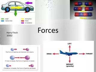
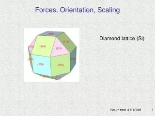
Forces, Orientation, Scaling Diamond lattice (Si) Picture from U of UTAH
Directions and Planes in Crystals Directions (vector components: a single direction is expressed as [a set of 3 integers], equivalent directions (family) are expressed as < a set of 3 integers > Planes: a single plane is expressed as (a set of 3 integers h k l = Miler indices) and equivalent planesare expressed as {a set of 3 integers} Miler indices: take a,b,c (multiple of basic vectors ex. x=4a, y=3a, z=2a) reciprocals (1/4, 1/3, 1/2)-> common denominator (3/12, 4/12, 6/12) -> the smallest numerators (3 4 6) lattice constant Plummer
Properties of crystals are determined by their orientation Diamond lattice of Si viewed in: <100> <110> <111> (111) (100) (100) (110) (111) go to http://stokes.byu.edu/diamond.htm to rate the crystal and see lattice symmetry. You can also calculate angles between various crytallographic planes and access many “clickable” material/device/process parameters calculated here http://www.ee.byu.edu/cleanroom/EW_orientation.phtml?flag=topic_index
Crystallographic orientation of Si Charges in MOS systems (measured in C-V) and many other properties depend on crystal orientation.
Orientation of Silicon Wafers is Important for MEMS Primary and Secondary Flats After Shimura
Stress and Strain Static and dynamic behaviors of MEMS under loading determined by Newton Laws Orientation effects are coming soon Basic mechanical engineering info can be found here on http://en.wikipedia.org/wiki/Main_Page using Force, Stress, Strain, Hook’s Law, Newton's laws of motion as key words, etc. as well as http://www.ami.ac.uk/courses/topics/0123_mpm/index.html
Force balance analysis (Traverse direction) Force and moment balance analysis Examples of Mechanical Structures remove the wall The wall reacts on the bar with an axial force=F (see “-” sign) A pair of forces create a torque (“couple” or “moment”) Newton 3rd Law F=0 Newton 1-st Law: total force=0 Liu
Shear Stress and Strain Pa Poisson’s ratio imaginary cut • Definition of normal Stress and Strain • Shear stress does not cause elongation or shortening of the element but deformation. • Shear strain represents angular displacement Normal Stress can be tensile or compressive Strain refers to elongation (“normal strain” if it is to area A) E is modulus of elasticity or Young’s modulus (intrinsic material property) G=Shear modulus of elasticity (later) G is material not dimension property
Deformations along the load (force F) and perpendicular to the load lead to an axial strain and a transverse strain: sl is tensile and st is compressive so they have opposite signs Poisson’s Ratio v (Poisson’s ratio) typically is ≈ 0.3-0.5. for metals ≈ 0.3, for rubber 0.5, for cork ≈0 (does not expand at all), polysilicon 0.22.
Mechanical Stress and Strain • Stress causes elongation and reduction of the cross-sectional area. Poisson’s ratio v describes this effect • Stress and strain, for small deformations, are described by Hooke’s law E is modulus of elasticity or Young’s modulus Shear modulus of elasticity G: For isotropic materials: K is bulk modulus representing volume change under pressure (water K=1E9 N/m2, Al K=7E10, steel K=14E10 N/m2
Scalar Relation Between Stress and Strain Generic stress-strain curve Non-generic Stress-strain relations • Important properties of materials used in MEMS: ductility, toughness, hardness, brittleness. Sign of applied load is important - some materials will fail “at lower stresses in shear, others in tension”. • Fatique failure is also important in MEMS - materials can develop cracks or weak points specially if operating under stress and/or harsh conditions. Thin films (<100 nm) can even work trillions of cycles w/o failure. Hooke's law=material deforms linearly with load
Silicon and Related Thin Films • Dimensions, crystal orientation affect mechanical properties of silicon: • Young’s modulus in c-Si: • In {100} planes: in direction of [110] 168GPa>[100] 130GPa • In {110} planes: [111] 187 GPa • Young’s modulus in poly-Si (120-160 GPa) depends on structure and grains therefore depends on processing • deposition conditions and subsequent annealing are important • Shear modulus depends on crystal orientation • Poisson’s ratio for c-Si varies from 0.055 to 0.36 and for poly-Si it is 0.15-0.36. • See Appendix A for specific data.
General Stress-Strain Relations • Stress and strain are tensors. Use matrix to express normal stress components xx yy zz (noted as T1-T3) and shear stress yz, xz, xy (noted as T4-T6) as vectors. s1-s2 are three independent strains, s4-s6 are three shear strains. C is the Stiffness matrix s- Strain matrix: S is the compliance matrix:
Example for Silicon Orientation Effects C matrix is very much simplified for Si along <100> direction It can be used to calculate normal stress components T1, T2, T3 and find Young’s modulus (see Example 3.5 for E[100]=T1/s1=130GPa)
Flexural Beam Bending Analysis Under Simple Loading Conditions Beams are described by how they are supported and how load is applied. degree of freedom cantilevers are basic MEMS structures no movement at the support rotation is restricted linear movement and rotation allowed Liu
Load and Boundary Conditions There is always a direct relation between the deflection and the load (for any boundary conditions) Kovacs
Bending of Cantilevers Under Various Boundary Conditions Liu
Longitudinal Strain Under Pure Bending and Deflection of the Beams h “I”=moments of inertia, which for a beam with rectangular cross section is Strain depends on total torque M smax=Mt/2EI M=bending moment or total torque A more complex case since the Moment along the beam is not constant. It is important to find the maximum displacement of a cantilever. under compression “tu” – neutral axis under tension equal max values of tensile and compressive stress max! Maximum stress is constant through the length of the beam Liu
Finding Spring Constants “k” Stiffness is characterize by the spring constant k (or force constant). To see how changes in the weight of an object and spring properties (length, stiffness, stretch) affect mechanical response of the system - watch these video. They show how scaling is used in MEMSs http://streamer.cen.uiuc.edu/me_mems/Video2.wmv http://streamer.cen.uiuc.edu/me_mems/Video3.wmv More can be found in http://www.engr.uiuc.edu/OCEE/outreach.htm.
Cantilevers Bending of a cantilever (by the angle and deflecting by x) depends on force, geometry and Young’s modulus. so the spring constant is: The stiffness depends on the force direction and on the direction of bending. The beam “is said that provide compliance in one direction and resistance to movement in another”. Spring constant decreases with length. Soft material (small E) would deform more so spring constant is small. Liu
Force Constants of Beams Various Applications of Mechanical Structures Force can be of various origin Liu
Applications of Mechanical Structures Selected from many: • Accelerometer is shown in this http://streamer.cen.uiuc.edu/me_mems/Video6.wmv • in http://www.engr.uiuc.edu/OCEE/outreach.htm 2. Digital Mirrors made by Texas Instruments (will come soon in Chapter 4) http://www.dlp.com/Default.asp?bhcp=1
The spring constant k associated with each fixed-guided beam Plates (thick) and Membranes (thin) Each spring shares the load so for plates supported by two fixed-guided beams it is and by four fixed-guided beams it is Liu
Torsional Deflection Maximum shear stress in the bar is max and it is distributed along the bar. Maximum shear strain is Maximum shear stress is related to the torque Torsional moment of inertia=J for a circular bar and square-cross section For the circular beams: the magnitude of the maximum shear stress is and the angular displacement of the torsional bar is Liu
Intrinsic Stress Internal stress can be present if layered structures are made. It is due to fabrication processes that use materials/processes that have different thermo-mechanical properties. Intrinsic stress can be uniform within a layer or have gradients in its distribution across the film thickness. Removal of the substrate layer releases the stress but causes deformation. Warped film Liu
Intrinsic Stress Introduced by Fabrication and Process History Liu
Measuring of Intrinsic Stress Testing of planar (large) areas. Testing local deformation/stress Horizontal beams under intrinsic stress Liu
Measuring of Intrinsic Stress Uniform compressive stress causes elongation or buckling of a double supported beam. Both tension and compression stress can be measured by such structures. Ring and beam structure For tensile stress in the ring when relaxed (underlying film released by etching) the ring expands and makes the beam compressed - up to the point of buckling (optical microscopy) Kovacs
Measuring of Intrinsic Stress if There is a Stress Gradient Nonuniform stress in the film causes the film to curl. If stress gradient is positive (larger away from the substrate) the spiral will open as a bowl. If stress gradient is negative (smaller away from the substrate) the spiral will buckle down. Each type requires anchoring either in the center or at the perimeter. Kovacs
Measuring of Intrinsic Stress Piezoelectric or piezoresitive sensor respond to curling of the film. Kovacs
Dynamics of the Beam Lumped mechanical structure is described as follows: Any force can act as an external force: gravity, electrostatics etc. If the force has frequency dependence it will cause mechanical oscillations where the amplitude will be affected by “damping”. Damping is due to drag forces and/or to deformation in the sprig or other parts. Kovacs
Analogy to Electrical Filters At resonance, the deflection is Q times larger than in steady state. Damping is represented by resistance, which reduces the quality factor Q Working as in DC
Multifunctional Sensors Integration of various functions possible in array sensors Control of arrays’ parameters (material & dimensions spring constant oscillation frequency & deflection) is ensured by IC technology Characterization techniques known in various science disciplines will have significantly improved sensitivity if used on the “diving boards”. Bending and oscillation depend on stress and mass
Smart Force Sensors: Cantilevers Physical and Chemical Functions of Cantilevers • Transduce signals from almost every domain to nanomechanical motion(bend/oscillate) • thermal • chemical • biochemical (no labeling • for biding recognitions) • biological • magnetic • electrical • optical • mechanical (stress) • Have high sensitivity (force 1.4x10⁻¹⁸N/Hz1/2, pH 1nm/5x10-5, mass 1fg/Hz) and high speed • Use minute quantities of analytes • Fabricated by IC processing: • Si, Si3N4 with sensitizing films • for tailored applications • Dimensions: µm range Bimetal AFM Origin 10-5 K Bending: 0.05 Å) phase transformation H2 & O2 on Pt SAM pW fJ active layer (Au) photo induced stress absorption swelling 1.1 Hz/fg pJ viscosity temperature mH2O≈ng in zeolite m(T) or magnetic alloys magnetic moment: 10-12 Am2 interface charges voltamograms pN (5.6x10⁻¹⁸N)
Cantilever Arrays for Multifunction Sensors Operation of cantilever arrays with various coatings • Signal Detection: • Electrical (Piezoresistors) • Optical (laser detection systems) • static mode (bending) • dynamic mode (tracking of resonance frequency) • Future: Wireless (magnetic) Position-Sensitive-Detector signal pre-processing Integration with optoelectronics for miniaturization and functionality IBM Zurich/Concentris/Basel University
Identification and Elimination of Artifacts Versatility of cantilevers allows to diminish main artifact effects: flow and temperature nonuniformity Differential measurements with a reference cantilever
Fabrication of Cantilevers Using Si Technology ITE, Poland
Fabrication of Piezoresistors Cantilevers ITE, Poland
Measurements of Differencial Deflection Two cantilevers covered by single stranded DNA. baseline Bending of the first cantilever by hybridization. Bending of the second cantilever by hybridization. Differential Bending also increases with concentrations The cantilevers bend by docking of molecules
Single Cell Detection Anti-E. coli antibodies Si3N4 L=15-400 µm W=5-50 µm Attachment of heat killed E. coli in various colonies Cell dimentions: 1.46 µmx730 nmx350nm 15x5 µm 5µm JVST B, J. Illic et al. 2001.
Force Amplified Biological Sensors 0.5 pN force removes nonspecifically bound particles sensitivity pg/l NRL, Baselt et al.
(Galis and Khatri, 2002) Outward arterial remodeling Normal artery Foam cell/macrophage-driven Unstable plaque Constrictive arterial remodeling Stable plaque Smooth muscle cell-driven