Download
1 / 41
420 likes | 544 Views
This presentation explores the intricacies of data center transport mechanisms, particularly focusing on congestion control algorithms such as QCN and TCP-RED. It discusses the evolution of data centers, the importance of efficient network interconnects, and how advancements in virtualization and resource pooling optimize server utilization. Furthermore, it delves into common challenges in high-speed Ethernet networks, emphasizing the need for effective congestion control strategies to ensure low latency and high throughput. Join us as we unveil the engineering principles behind the convergence of network and storage technologies.

E N D
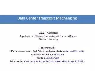
Data Center Transport Mechanisms Balaji Prabhakar Departments of Electrical Engineering and Computer Science Stanford University Joint work with: Mohammad Alizadeh, Berk Atikoglu and Abdul Kabbani, Stanford University Ashvin Lakshmikantha, Broadcom Rong Pan, Cisco Systems Mick Seaman, Chair, Security Group; Ex-Chair, Interworking Group, IEEE 802.1
What are Data Centers? • Large enterprise networks; convergence of • High speed LANs: 10, 40, 100 Gbps Ethernet • Storage networks: Fibre Channel, Infiniband • Related idea: Cloud Computing • Outgrowth of high-performance computing networks with integrated storage and server virtualization support • Driven by • Economics: One network, not many • Low capex and opex • Economics: Server utilization • Resource pooling, virtualization, server migration, high-speed interconnect fabrics • Savings in power consumption • Unified management of network of servers allows server and job scheduling • Security • Storage and processing of data within a single autonomous domain
Overview of a Data Center N-Tiers of Servers (Web, App, Database) Front End Networks (Security & Load Balancing) DataStorage • Large networks of servers, storage arrays, connected by a high-performance network • Origins • Clusters of web servers • Web hosting • High performance computing: Cloud computing • Servers, storage FC Firewall VPN Disk and Tape IDS IP Load Balancing • Key drivers • Convergence of Layer 2 neworks • Swtiched Ethernet (LANs) and Storage Area Networks (SANs): FCoE • Server virtualization • VMs, VM migration NAS & File Storage IB Data Center
Rest of the Talk • A brief overview of the relevant congestion control background • A description of the QCN algorithm and its performance • The Averaging Principle: A control-theoretic idea underlying the QCN and BIC-TCP algorithms which stabilizes them when loop delays increase; very useful for operating high-speed links with shallow buffers---the situation in 10+ Gbps Ethernets
Why do Congestion Control? • Congestion: Transient: Due to random fluctuations in packet arrival rate • Handled by buffering packets, pausing links (IEEE 802.1bb) Sustained: When link bandwidth suddenly drops or when new flows arrive • Switches signal sources to reduce their sending rate: IEEE 802.1Qau • Congestion control algorithms aim to • Deliver high throughput, maintain low latencies/backlogs, be fair to all flows, be simple to implement and easy to deploy • Congestion control in the Internet: Rich history of algorithm development, control-theoretic analysis, deployment • Jacobson, Floyd et al, Kelly et al, Low et al, Srikant et al, Misra et al, Katabi, Paganini, et al
A main issue: Stability • Stability of control loop • Refers to the non-oscillatory behavior of congestion control loops • If the switch buffers are short, oscillating queues can overflow (and drop packets) or underflow (lose utilization) • In either case, links cannot be fully utilized, throughput is lost, flow transfers take longer
TCP--RED: A basic control loop TCP TCP TCP TCP p qavg minth maxth RED: Drop probability, p, increases as the congestion level goes up TCP: Slow start + Congestion avoidance Congestion avoidance: AIMD No loss: increase window by 1; Pkt loss: cut window by half
TCP Dynamics Cwnd Congestion Window ~ Rate Cwnd/2 Time Congestion message recd
TCP--RED: Analytical model 1/R C - q - Time Delay p TCP Control RED Control
TCP--RED: Analytical model Users: Network: W: window size; RTT: round trip time; C: link capacity q: queue length; qa: ave queue length p: drop probability *By V. Misra, W. Dong and D. Towsley at SIGCOMM 2000 *Fluid model concept originated by F. Kelly, A. Maullo and D. Tan at Jour. Oper. Res. Society, 1998
TCP--RED: Stability analysis • Given the differential equations, in principle, one can figure out whether the TCP--RED control loop is stable • However, the differential equations are very complicated • 3rd or 4th order, nonlinear, with delays • There is no general theory, specific case treatments exist • “Linearize and analyze” • Linearize equations around the (unique) operating point • Analyze resultant linear, delay-differential equations using Nyquist or Bode theory • End result: • Design stable control loops • Determine stability conditions (RTT limits, number of users, etc) • Obtain control loop parameters: gains, drop functions, …
Instability of TCP--RED • As the bandwidth-delay-product increases, the TCP--RED control loop becomes unstable • Parameters: 50 sources, link capacity = 9000 pkts/sec, TCP--RED • Source: S. Low et. al. Infocom 2002
Feedback Stabilization • Many congestion control algorithms developed for “high bandwidth-delay product” environments • The two main types of feedback stabilization used are: • Determine lags (round trip times), apply the correct “gains” for the loop to be stable (e.g. FAST, XCP, RCP, HS-TCP) • Include higher order queue derivatives in the congestion information fed back to the source (e.g. REM/PI, XCP, RCP) • We shall see that BIC-TCP and QCN use a different method which we call the Averaging Principle • BIC (or Binary Increase) TCP is due to Rhee et al • It is the default congestion control algorithm in Linux • No control theoretic analysis, until now
Quantized Congestion Notification (QCN): Congestion control for Ethernet
Ethernet vs. the Internet • Some significant differences … • No per-packet acks in Ethernet, unlike in the Internet • Not possible to know round trip time or lags! • So congestion must be signaled to the source by switches • Algorithm not automatically self-clocked (like TCP) • Links can be paused; i.e. packets may not be dropped • No sequence numbering of L2 packets • Sources do not start transmission gently (like TCP slow-start); they can potentially come on at the full line rate of 10Gbps • Ethernet switch buffers are much smaller than router buffers (100s of KBs vs 100s of MBs) • Most importantly, algorithm should be simple enough to be implemented completely in hardware • Note: QCN has Internet relatives---BIC-TCP at the source and the REM/PI controllers
Data Center Ethernet Bridging:IEEE 802.1Qau Standard • A summary of standards effort • Everybody should do it at least once • Like proving limit theorems in Probability • But, in this case, no more than once!? • Intense, fun activity • Broadcom, Brocade, Cisco, Fujitsu, HP, Huawei, IBM, Intel, NEC, Nortel, … • Conference calls every Thursday morning • Meeting every 6 weeks (Interim and Plenary) • Real-time engineering: Tear and re-build • Our algorithm was the 4th to be proposed • It underwent 5—6 revisions because of being “subjected to constraints” • Draft of standard: 9 revs
QCN Source Dynamics TR Target Rate CR Rd/8 Rd/4 Rd Rate Rd/2 Current Rate Time Congestion message recd TCP – AIMD Rate BIC-TCP and QCN Congestion message recd Time
Stability: AIMD vs QCN AIMD QCN RTT = 50 μs RTT = 300 μs
Experiment & Simulation Parameters • Baseline scenario • Output-queued switch • OG hotspot; hotspot severity: 0.2Gbps, hotspot duration ~3.5sec • Vary RTT: 100us to 1000us 0.95 G 0.95 G NIC 1 0.2 G NIC 2
1 source, RTT = 100μs Hardware OMNET++
1 source, RTT = 1ms Hardware OMNET++
8 sources, RTT = 1ms Hardware OMNET++
Fluid Model for QCN P = Φ(Fb) • Assume N flows pass through a single queue at a switch. State variables are TRi(t), CRi(t), q(t), p(t). 10% Fb 63
QCN Notes • The algorithm has been extensively tested in deployment scenarios of interest • Esp. interoperability with link-level PAUSE and TCP • All presentations and p-code are available at the IEEE 802.1 website: http://www.ieee802.org/1/pages/dcbridges.html http://www.ieee802.org/1/files/public/docs2008/au-rong-qcn-serial-haipseudo-code%20rev2.0.pdf • The theoretical development is interesting, but most notably because QCN and BIC-TCP display strong stability in the face of increasing lags, or, equivalently in high bandwidth-delay product networks • While attempting to understand the unusually good performance of these schemes, we uncovered a method for improving the stability of any congestion control scheme
The Averaging Principle (AP) • A source in a congestion control loop is instructed by the network to decrease or increase its sending rate (randomly) periodically • AP: a source obeys the network whenever instructed to change rate, and then voluntarily performs averaging as below TR = Target Rate CR = Current Rate
A Generic Control Example • As an example, we consider the plant transfer function: P(s) = (s+1)/(s3+1.6s2+0.8s+0.6)
Step Response Two-step AP, Delay = 25 seconds Two-step AP is even more stable than Basic AP
Applying AP to RCP (Rate Control Protocol)RCP due to Dukkipatti and McKeown • Basic idea: Network computes max-min flow rates for each flow. • Rate computed every 10 msecs • Flows send at their advertised rate • Apply the AP to RCP
AP-RCP Stability RTT = 60 msec RTT = 65 msec
AP-RCP Stability cont’d RTT = 120 msec RTT = 130 msec
AP-RCP Stability cont’d RTT = 230 msec RTT = 240 msec
Understanding the AP • As mentioned earlier, the two major flavors of feedback compensation are: • Determine lags, chose appropriate gains • Feedback higher derivatives of state • We prove that the AP is sense equivalent to both of the above! • This is great because we don’t need to change network routers and switches • And the AP is really very easy to apply; no lag-dependent optimizations of gain parameters needed
AP Equivalence Source does AP Fb Regular source 0.5 Fb + 0.25 T dFb/dt • Systems 1 and 2 are discrete-time models for an AP enabled source, and a regular source respectively. • Theorem: Systems 1 and 2 are algebraically equivalent. That is, given identical input sequences, they produce identical output sequences.
Conclusions • We have seen the background, development and analysis of a congestion control scheme for the IEEE 802.1 Ethernet standard • The QCN algorithm is • More stable with respect to control loop delays • Requires much smaller buffers than TCP • Easy to build in hardware • The Averaging Principle is interesting; we’re exploring its use in nonlinear control systems