Download

1 / 29
300 likes | 498 Views
Design and Development of a CubeSat De-Orbit Device. Team Members. An Kim Cian Branco David Warner Edwin Billips Langston Lewis Thomas Work Mackenzie Webb Benjamin Cawrse (CS) Jason Harris (TCC). Introduction. Thousands of man made objects in earth orbit (mostly junk).

E N D
Team Members • An Kim • CianBranco • David Warner • Edwin Billips • Langston Lewis • Thomas Work • Mackenzie Webb • Benjamin Cawrse (CS) • Jason Harris (TCC)
Introduction • Thousands of man made objects in earth orbit (mostly junk). • Debris can be a serious hazard to satellites. • A paint flake threatened the Space Shuttle; a Russian Satellite disabled an Iridium satellite
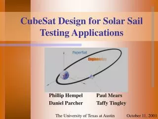
Introduction • CubeSatsare picosatellitesused by universities and institutions for research in space. • Pending international treaty will require future launch stages and LEO satellites to deorbitwithin 25 years of mission completion. • Objective: design and test a de-orbit system to de-orbit CubeSats within 25 years of mission completion.
Objectives • Demonstrate commercial viability • Prove it is a robust and viable system • Achieve these objectives with a minimum cost • Orbital demonstrator • Suborbital flight • High altitude balloon flight
Objectives • Demonstrate commercial viability • Prove it is a robust and viable system • Achieve these objectives with a minimum cost • Orbital demonstrator • Suborbital flight • High altitude balloon flight
Objectives • Demonstrate commercial viability • Prove it is a robust and viable system • Achieve these objectives with a minimum cost • Orbital demonstrator • Suborbital flight • High altitude balloon flight
Objectives • Demonstrate commercial viability • Prove it is a robust and viable system • Achieve these objectives with a minimum cost • Orbital demonstrator • Suborbital flight • High altitude balloon flight
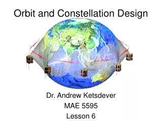
RockSat-X Program • The RockSat-X program out of Wallops Flight Facility is currently considered the best option for our test flight • RockSat-X utilizes the Terrier-Improved Malemute suborbital sounding rocket • The sounding rocket will reach apogee at approximately 160 km altitude from the Earth.
Advantages of RockSat-X • 300 seconds of microgravity flight • Power and telemetry on deck provided for timing devices, communication between ground and payload, and data storage • Direct access to orbital space after second stage burn-out when the skin of the sounding rocket is ejected. • Adequate space and weight capacity available to mount the deployment device and necessary telemetry for the mission of our CubeSat
Electronics Langston Lewis
Power • Lithium-Ion batteries will be used to supply power to the board and release mechanism. • Can sustain high amounts of continuous current discharge in order to run the camera and communications devices. • Mass of batteries is a concern
Arduino Board • Stable operation between 6-20 volts • 14 digital and 6 analog pins • Board has built in accelerometers
Strain Gauge • Mounted on aero brake support structure. • Voltage differences can be converted to strain and then used to calculate drag coefficient produced by balloon
Video Acquisition • 160x120 resolution • Support capture JPEG from serial port • Default baud rate of serial port is 38400 but we will be transmitting at 19200 • Works reliably with 5v power supply • Size 32X32mm • Consumes between 80-100 mA of current
Radio Communication • Low-power and weight in an equally small size • Provides adequate resolution and range
Aerodynamic Brake • Objective: • Mylar Balloon • Test benzoic acid inflations under different temperature than the sublimating temperature • Calculate the correct benzoic acid mass to inflate the Mylar balloon within the vacuum chamber • Record time for the benzoic acid to fully inflate • Nitinol (SMA)
Aerodynamic Brake • Temperature for benzoic acid inflation • From Emerald Performance Materials, estimated sublimation temp is C • A thermistor will be use to vary temperature when testing benzoic acid inflation
Aerodynamic Brake • Mass of benzoic acid • The required amount of benzoic acid will be less than 0.1 gram. • The mass may vary to increase the rate of inflation http://social.rollins.edu/wpsites/chm220th/files/2011/09/photo-4.jpg
Aerodynamic Brake • Time Limit • Must inflate in under 300 seconds • Goal of the experiment is to have the Mylar Balloon to inflate in less than 200 seconds.
O-POD Design David Warner Cian Branco
O-POD Overview • ODU Picosatellite Orbital Deployer • Bolted to Rocksat-X deck, “piggybacks” rocket • Directly connected to RS-X Power Interface (1 A-h) • Stores, imparts ejection velocity to CubeSat • 1.6 m/s from spring, lateral to deck • Al-7075-T651 frame • 1.477 kg total mass
O-POD Specifications • Materials • 7mm thick Al-7075 plates • Holes can be cut for RS-X power interface & instruments • 42 + 12 bolts (M4 x0.70 10mm) • ASTM-A228 “Music Wire” Spring • 19.62cm length (entire) • 7 turns coil • Held by crossbar on back plate • Supports pusher-plate • ~1.5 kg total • Overall Dimensions • 12.7cm x 12.7 cm x 19.62 cm
Design Concerns • 5 design iterations, still not space-rated • Weak pusher-plate to spring connection • Torsion in spring, friction issues on rails • CubeSat mockup “f” varies w/ humidity (cardboard) • Aluminum mockup in the works • Lubrication? • Quick Release Mechanism Options • Vectran Line Cutter (ODU built) • 2 Linear Solenoids • Center-of-Mass • Must be inside 2” square at center
Future Work • Further PATRAN & FEA analysis (vibrations accountable) • Resume velocity measurements with new mockup • Choose quick release mechanism within budget • Design a mounting plate to connect O-POD to RockSat-X
Conclusion • Most of our time so far has been allocated to gathering information, resources and planning • We will apply that information to create prototypes and perform the necessary experimental tests for the successful mission of our CubeSat • All tests and prototypes will be performed and created to interface with RockSat-X, but we will consider other options for test flights as well.