
Guide to Network Cabling Fundamentals
E N D
Presentation Transcript
Guide to Network Cabling Fundamentals Chapter 5
Chapter 5 - Backbone and Horizontal Distribution Systems • Understand backbone distribution systems • Discuss the types of cross-connection in a backbone system • Differentiate between interbuilding and intrabuilding backbone systems
Chapter 5 - Backbone and Horizontal Distribution Systems • Understand horizontal distribution systems • Discuss design guidelines and work areas in horizontal distribution systems • Document the cable plant • Document equipment rooms
Backbone Distribution Systems • Backbone distribution systems connect the equipment rooms, telecommunications rooms (TRs), and entrance facilities • Two types of connections exist: intrabuilding, are made between the floors of multistory buildings; and interbuilding, those made between buildings • Intrabuilding backbones link all of a building’s cross-connects, which mechanically terminate and administer building wiring • Interbuilding backbones link intermediate cross-connects in other buildings to the main cross-connect
Backbone Distribution Systems • All backbone cabling in the distribution system links three types of cross-connects: • Horizontal cross-connects (HCs), which consist of horizontal cabling using jumpers, patch cords and other hardware; main cross-connects (MCs), the primary connection and flexibility point within a network; and intermediate cross-connects (ICs) between first- and second-level backbones • Backbone cabling connects the equipment and runs from the equipment room to the various TRs; depending on the size of the building(s) involved, these TRs house either the ICs or the HCs
Backbone Distribution Systems • Intrabuilding backbones: • Consist of multipair copper or optical-fiber cables and their supporting hardware • Connect all the HCs or ICs in a building to the MC • ANSI/EIA/TIA-568-A standard requires all backbone cabling to be a star or hierarchical star topology • Backbone topology differs from that of a network in the following ways: they connect multiple network segments; they can connect and support different topologies; they provide support for all modes of communication
Backbone Distribution Systems • Intrabuilding backbones (cont.): • In the star topology, individual nodes are linked to the HC, which is connected directly to the MC • In hierarchical star, some or all of the HCs are linked to an IC, which in turn is linked to the building’s MC • In general, the star topology is the better design choice, unless in large buildings, such as high-rises • Choose the topology based on: the types and sizes of cable available; the hardware necessary; the size of the site and number of end users; the installation labor required; the applications used
Backbone Distribution Systems • Interbuilding backbones: • Link the HC or IC in various buildings to the MC • Is the network segment that gives distributions designers and users the most options, but is also most affected by physical considerations • ANSI/EIA/TIA-568-A standard requires interbuilding backbones to be the hierarchical star topology • The better design for small networks is a single-level hierarchical star because: it provides a single point of control; allows testing and reconfiguration; easier maintenance and security; increased flexibility
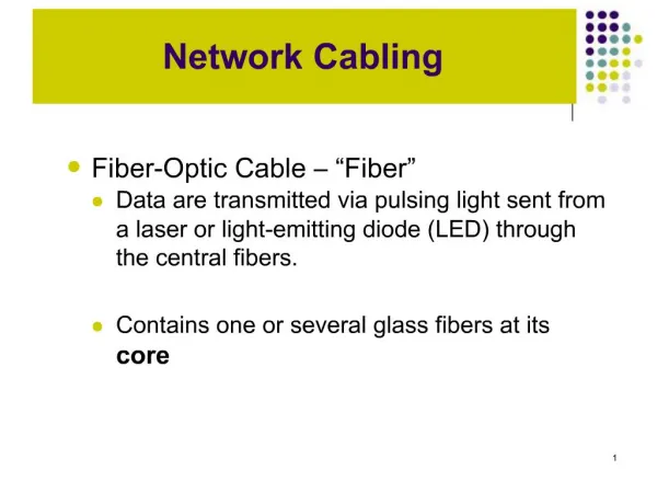
Backbone Distribution Systems • Selecting backbone distribution media considerations: • The recognized cable types are: multimode optical fiber; single-mode optical fiber; 100-ohm twisted-pair • Often a single cable type will not satisfy all user requirements and if more that one medium is used, make sure they all use the same facility architecture • Consider the following factors when choosing medium: its flexibility with respect to the supported services; the required useful life; the size of the site and number of users
Backbone Distribution Systems • Selecting backbone distribution media (cont.): • Whenever possible, first determine the different service requirements, then group them into similar services, such as voice, display terminal, LAN, and other digital connections; next identify the individual media types and project each group’s quantities • When deciding on backbone cable size, first know how many workstations are served by each TR and how many pairs the horizontal cabling provides • When selecting backbone cable, know the maximum backbone distances for each medium
Backbone Distribution Systems • Selecting backbone distribution media (cont.): • Fiber cables are available with different sheaths for indoor (intrabuilding) and outdoor (interbuilding) • Backbone fiber cable consists of optical fibers with individually colored buffer jackets of flame-retardant polymer; the cable is stranded around central strength member, providing a rugged cable • When using fiber for the backbone, plan to use at least a six-fiber cable for each TR, however, a 24-fiber cable is highly recommended; typically fibers reserved are: six for LANs, six for redundancy, and twelve for growth
Backbone Distribution Systems • Selecting backbone distribution media (cont.): • Plastic insulated conductor (PIC) cable is twisted-pair designed to ease cable-pair identification • Each pair is color-coded in groups of 25 pairs; these pairs are placed together in a binder group, which is identified by a color-coded binder wrapping • PIC cables are usually available in sizes ranging from 6 to 4200 pairs • The cables are manufactured in various designs for aerial, buried, underground, and in-building applications
Backbone Distribution Systems • Selecting the main cross-connect hardware: • The main cross-connect is the primary connection and flexibility point within a network • Depending on the number of copper pairs necessary to terminate at the main cross-connect, the cross-connection hardware can be wall- or rack-mounted • The main cross-connect is generally located in the equipment room; when selecting the location for this room, consider that the room should be: accessible for large equipment delivery, not constricted for expansion, not below the water level
Horizontal Distribution Systems • This cabling system provides: • The physical means for transporting signals between the telecommunications outlet/connector in the work area and the HC in the TR • The cabling and its associated connecting hardware make up the horizontal pathways • These pathways include the cable pathway itself, as well as the related spaces, such as pull boxes, splice boxes, and intermediate consolidation points • The pathway design should allow for at least three cable runs per work area
Horizontal Distribution Systems • Horizontal distribution design guidelines: • The horizontal cabling is usually less accessible than other cabling, and is subject to the greatest amount of activity, so good design is crucial • A star topology must be used • Each telecommunications outlet in the work area must be directly connected to an HC in a TR on the same floor; the maximum distance for this is 90 m • For each horizontal cable, a maximum distance of 10 m is permitted for work area cords, patch cords, and jumpers, and any equipment cords
Horizontal Distribution Systems • Horizontal distribution design guidelines (cont): • Horizontal distribution system recommended media: four-pair, 100-ohm UTP cable; two-pair, 150-ohm STP-A; two-fiber fiber-optic cable • Hybrid cables contain multiple types of media under a single sheath; one that contains both fiber cable and copper conductors is called a composite cable • Points to consider when using hybrid cables: 100-ohm UTP cables of mixed categories should not reside within the same sheath; the cables of a hybrid cable must meet cross-talk specifications
Horizontal Distribution Systems • Work area components for horizontal distribution: • Work area cables are the modular cords that connect the telecommunications outlet to the work area equipment • The modular cord in the work area should have a maximum length of 3 m, and all four-pair UTP cables must be terminated in eight-position modular jacks (RJ-45) in the work area, following T-568 • The connector must be mounted on the outlet faceplate to make it accessible for work area connectors
Horizontal Distribution Systems • Horizontal cables and their cross-connects: • Link each telecommunications outlet to the HC with a dedicated 4-pair, 24-AWG, Cat 5 UTP cable; the length of this cable should not exceed 90 m • The HC consists of cable terminations and cabling hardware to help link the horizontal cables to the telecommunications and control equipment • Use the BIX or 110 IDC cross-connect system with modular RJ-45 patch panels to connect voice/data • The HC is located in the TR; each floor should have at least one TR
Documenting the Cable Plant • The cable plant: • Includes all cables and termination points in an installation, such as the work area outlets, patch panels, and punch-down blocks • This information is probably the most useful and important component of the documentation - once cables are run through ceilings and floors and terminated, finding a particular cable that is causing problems is next to impossible if it wasn’t labeled; also it tells you which cables can and cannot be disconnected when you move equipment
Documenting the Cable Plant • Documenting cable types and Terminators: • Begin the cable plant documentation by describing the types of cables in use, their purposes, and the types of terminators used • In addition, list any exceptions that were made during installation • Use a cut sheet to include information on the connection made by the cable, the length of the run, the cable ID and type of cable, the patch-panel port, whether the cable is in use or not, and any testing done and the results of such
Documenting the Cable Plant • Labeling: • Label all cable runs, equipment, patch panels, and jacks with a name/number clearly identifying them • Document cable test results and problems with the cable plant • Once a cable passes its requisite tests, label it and move on to the next cable • When there are any concerns about the cable plant, include them in the documentation
Documenting Equipment Rooms • Equipment rooms must be documented: • Include the room location and room dimensions, as well as the types of doorways, ceilings, walls, cooling, heating, and lighting used • All of the cables in the equipment room must be documented, as well as those in the building areas each room serves • Describe devices and their location in each room, including their capacities; before adding workstations in any area, determine whether patch panels, hubs, and switches have available ports
Documenting Equipment Rooms • Documenting power considerations: • Many network devices require considerable power to operate, and some even have special electrical outlet requirements; most major equipment comes with redundant power supplies • Examine each equipment room to determine the type and number of power outlets, document the power budget, including total power, and how much power is in use • Most equipment rooms use an uninterruptible power supply (UPS); document each UPS
Documenting Equipment Rooms • Diagramming equipment racks and installed equipment: • Provide detailed drawings of your equipment racks, with the installed devices shown and labeled • Include the rack name and location; the patch panel name, type and ports; the hub name, type and ports; the UPS name and type • Documenting known problems or concerns with equipment rooms • Include information about any rooms that do not meet specifications for cooling, power, or lighting
Chapter Summary • Backbone distribution systems provide the interconnections between telecommunications rooms, equipment rooms, and entrance facilities. The two types of backbone distribution systems are the interbuilding system, which connects other buildings to the main cross-connect, and the intrabuilding system, which provides connections between the floors of a multistory building • The maximum recommended distances for backbone cables depend on their application. For example, the maximum distance for data applications is 90 m. For voice applications, the maximum distances vary
Chapter Summary • When planning multipair (backbone) cable spaces, you should stay as far away as possible from power cables, transformers, electrical motors, and fluorescent lighting • A typical fiber backbone installation consists of one fiber-optic cable, usually in counts of 6, 12, or 24 fibers, that runs between the main cross-connect and each TR • Backbone distribution systems usually employ a hierarchical star topology with one or more levels. Horizontal distribution systems use a simple star topology
Chapter Summary • The horizontal distribution is the part of the cabling system used to distribute, support, and provide access to the horizontal cabling. This cabling system provides the physical means for transporting signals between the telecommunications outlet/connector in the work area and the horizontal cross-connect in the TR. The cabling and its associated connecting hardware make up the content of the horizontal pathway and related space
Chapter Summary • Work area components for horizontal distribution include telephones, fax, data terminals, and computers, plus any other items located between these components and the telecommunications outlet • Your cable plant documentation includes all the cables and termination points in an installation, such as work area outlets, patch panels, and punch-down blocks. The cable plant information is probably the most useful and important components of your documentation - once cables are run through ceilings and floors and terminated, finding a particular cable that is causing problems can be almost impossible if you didn’t label it
Chapter Summary • Describe each equipment room in detail in your documentation. Include information for all cable runs, devices, racks, power considerations, and known problems or concerns. This documentation makes additions and changes easier, provides port information to accommodate additions, and identifies all equipment and its locations