Download
1 / 15
150 likes | 292 Views
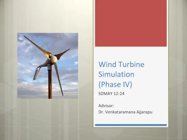
Development of Laboratory Module for a Small Wind Turbine System (Phase V). Team members: Adam Literski , Achila Jayasuriya , Eurydice Ulysses, Josephine Namatovu , Logeshwar Sampathkumar , Liaochao Song Client / Advisor : Dr. Venkataramana Ajjarapu. MAY1329. Slide 1 of 13.

E N D
Development of Laboratory Module for a Small Wind Turbine System (Phase V) Team members: Adam Literski, AchilaJayasuriya, Eurydice Ulysses, Josephine Namatovu, LogeshwarSampathkumar, Liaochao Song Client / Advisor: Dr. VenkataramanaAjjarapu MAY1329 Slide 1 of 13
Project Goals Develop a small wind turbine system in a laboratory environment Serve as an educational tool for independent or class purposes Use Digital implementation of power electronics using simulations on MATLAB ASMG and Code Composer Studio MAY1329 Slide 2 of 13
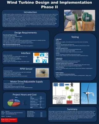
Project Deliverables • Project documentation user manual • Step-by-step operation instructions • In-depth schematics and wiring diagrams • Final Project Plan & Design Document MAY1329 Slide 3 of 13
Phase IV System Old system: • Induction motor has 1.5 Hp • Motor frequency controlled with a Variable Frequency Drive • NIDAQ Control Source • NI LabVIEW user interface Issues: • Buck boost IGBT burning out • System functioning not complete Figure 1: Variable Frequency Drive Figure 2: Phase IV System MAY1329 Slide 4 of 13
Current System Old system: • New motor run by TI drive kit • TI Control Suite user interface • Revised buck boost converter • Arduinofor voltage comparison • Voltage sensors in the system Picture of Entire System!!! Figure 3: Phase V System MAY1329 Slide 5 of 13
Overall System Figure 4: Overall System MAY1329 Slide 6 of 13
Motor And Generator Insert GUI of the Motor Signal sent from the TI kit to run the motor Figure 6: EMJ-04APB22 Motor coupled with Permanent Magnet Generator Figure 5: TMDSHVMTRPFCKIT MAY1329 Slide 7 of 13
Three – Phase Rectifier Figure 4: Rectifier Simulation Output Calculation Figure 7: Three-Phase Rectifier in ASMG MAY1329 Slide 8 of 13
Voltage Comparator Figure 8: Comparator schematic Slide 9 of 13
Pulse Width Modulation Using a ControlCARD, the duty cycle of the Buck /Boost converter is easily monitored Figure 9: ControlCARD Figure 10: Pulse Width Modulated Signal Figure 11: Graphical User Interface MAY1329 Slide 10 of 13
Buck / Boost Converter Figure 12: Buck/Boost schematic & simulation results Input voltage = 12V Depending on Duty Cycle Variable output Duty cycle = 70% (boost system) Duty cycle = 20% (buck system) Slide 11 of 13
Test Plan • Test system stability for various input voltages • Test system for a standard runtime • Battery backup implementation • Address three cases: • Power Generation > Load • Power Generation = Load • Power Generation < Load • Dissipate excess power generation MAY1329 Slide 12 of 13
Challenges Encountered And Solutions Challenges: Unavailability of Variable Frequency Drive Relevant knowledge base Discrepancy in old schematics Solutions: Motor replacement Relevant knowledge base from EE 452 (Power Electronics & Drives) labs Revision of the old system MAY1329 Slide 13 of 13
Demo INSERT VIDEO HERE!!
Questions May 1329: Development of a Small Wind Turbine System Client / Advisor: Dr. VenkataramanaAjjarapu