Download
1 / 27
270 likes | 409 Views
Top-Down Network Design ST - Fadi Shakhsa ID - 120100327 DR - Yasmen Elbobo. Topology. A term used in the computer networking field to describe the structure of a network. Network Topology Design Themes. Hierarchy Redundancy Modularity Well-defined entries and exits Protected perimeters.

E N D
Top-Down Network DesignST - FadiShakhsaID - 120100327DR - YasmenElbobo
Topology • A term used in the computer networking field to describe the structure of a network
Network Topology Design Themes • Hierarchy • Redundancy • Modularity • Well-defined entries and exits • Protected perimeters
Why Use a Hierarchical Model? • Reduces workload on network devices • Constrains broadcast domains • Enhances simplicity and understanding • Facilitates changes • Facilitates scaling to a larger size
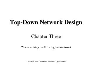
Hierarchical Network Design Enterprise WAN Backbone Core Layer Campus A Campus B Campus C Distribution Layer Campus C Backbone Access Layer Building C-1 Building C-2
Cisco’s Hierarchical Design Model • A core layer of high-end routers and switches that are optimized for availability and speed • A distribution layer of routers and switches that implement policies and segment traffic • An access layer that connects users via hubs, switches, and other devices
Mesh Designs Partial-Mesh Topology Full-Mesh Topology
A Partial-Mesh Hierarchical Design Headquarters (Core Layer) Regional Offices (Distribution Layer) Branch Offices (Access Layer)
A Hub-and-Spoke Hierarchical Topology Corporate Headquarters Branch Office Home Office Branch Office
A Simple Campus Redundant Design Host A LAN X Switch 1 Switch 2 LAN Y Host B
Bridges and Switches use Spanning-Tree Protocol (STP) to Avoid Loops Host A LAN X X Switch 1 Switch 2 LAN Y Host B
Lowest Bridge ID Wins! Elect a Root Bridge A ID = 80.00.00.00.0C.AA.AA.AA Root Bridge A Port 1 Port 2 LAN Segment 1 100-Mbps Ethernet Cost = 19 LAN Segment 2 100-Mbps Ethernet Cost = 19 Port 1 Port 1 Bridge B Bridge C Port 2 Port 2 Bridge B ID = 80.00.00.00.0C.BB.BB.BB Bridge C ID = 80.00.00.00.0C.CC.CC.CC LAN Segment 3 100-Mbps Ethernet Cost = 19
Determine Root Ports Bridge A ID = 80.00.00.00.0C.AA.AA.AA Root Bridge A Lowest Cost Wins! Port 1 Port 2 LAN Segment 1 100-Mbps Ethernet Cost = 19 LAN Segment 2 100-Mbps Ethernet Cost = 19 Root Port Root Port Port 1 Port 1 Bridge B Bridge C Port 2 Port 2 Bridge B ID = 80.00.00.00.0C.BB.BB.BB Bridge C ID = 80.00.00.00.0C.CC.CC.CC LAN Segment 3 100-Mbps Ethernet Cost = 19
Determine Designated Ports Bridge A ID = 80.00.00.00.0C.AA.AA.AA Root Bridge A Designated Port Designated Port Port 1 Port 2 LAN Segment 1 100-Mbps Ethernet Cost = 19 LAN Segment 2 100-Mbps Ethernet Cost = 19 Root Port Root Port Port 1 Port 1 Bridge B Bridge C Port 2 Port 2 Bridge B ID = 80.00.00.00.0C.BB.BB.BB Bridge C ID = 80.00.00.00.0C.CC.CC.CC LAN Segment 3 100-Mbps Ethernet Cost = 19 Designated Port Lowest Bridge ID Wins!
Prune Topology into a Tree! Bridge A ID = 80.00.00.00.0C.AA.AA.AA Root Bridge A Designated Port Designated Port Port 1 Port 2 LAN Segment 1 100-Mbps Ethernet Cost = 19 LAN Segment 2 100-Mbps Ethernet Cost = 19 Root Port Root Port Port 1 Port 1 Bridge B Bridge C Port 2 Port 2 X Bridge B ID = 80.00.00.00.0C.BB.BB.BB Bridge C ID = 80.00.00.00.0C.CC.CC.CC LAN Segment 3 100-Mbps Ethernet Cost = 19 Designated Port Blocked Port
React to Changes Bridge A ID = 80.00.00.00.0C.AA.AA.AA Root Bridge A Designated Port Designated Port Port 1 Port 2 LAN Segment 1 LAN Segment 2 Root Port Root Port Port 1 Port 1 Bridge B Bridge C Port 2 Port 2 Bridge B ID = 80.00.00.00.0C.BB.BB.BB Bridge C ID = 80.00.00.00.0C.CC.CC.CC LAN Segment 3 Designated Port Becomes Disabled Blocked Port Transitions to Forwarding State
Virtual LANs (VLANs) • An emulation of a standard LAN that allows data transfer to take place without the traditional physical restraints placed on a network • A set of devices that belong to an administrative group • Designers use VLANs to constrain broadcast traffic
VLANs versus Real LANs Switch A Switch B Station A1 Station A2 Station A3 Station B1 Station B2 Station B3 Network A Network B
VLAN A Station A1 Station A2 Station A3 Station B1 Station B2 Station B3 VLAN B A Switch with VLANs
VLAN A VLAN A Station A1 Station A2 Station A3 Station A4 Station A5 Station A6 Switch A Switch B Station B1 Station B2 Station B3 Station B4 Station B5 Station B6 VLAN B VLAN B VLANs Span Switches
WLANs and VLANs • A wireless LAN (WLAN) is often implemented as a VLAN • Facilitates roaming • Users remain in the same VLAN and IP subnet as they roam, so there’s no need to change addressing information • Also makes it easier to set up filters (access control lists) to protect the wired network from wireless users
HSRP Active Router Enterprise Internetwork Virtual Router Workstation Standby Router
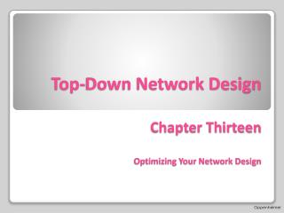
Paris NY NY Paris Multihoming the Internet Connection ISP 1 ISP 1 Enterprise Enterprise Option A Option C ISP 1 ISP 2 ISP 1 ISP 2 Enterprise Enterprise Option B Option D
Security Topologies DMZ Enterprise Network Internet Web, File, DNS, Mail Servers
Security Topologies Internet Firewall DMZ Enterprise Network Web, File, DNS, Mail Servers
Summary • Use a systematic, top-down approach • Plan the logical design before the physical design • Topology design should feature hierarchy, redundancy, modularity, and security