Download
1 / 62
630 likes | 787 Views
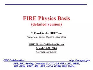
FIRE Collaboration. http://fire.pppl.gov. AES, ANL, Boeing, Columbia U., CTD, GA, GIT, LLNL, INEEL, MIT, ORNL, PPPL, SNL, SRS, UCLA, UCSD, UIIC, UWisc. FIRE Physics Basis (detailed version). C. Kessel for the FIRE Team Princeton Plasma Physics Laboratory FIRE Physics Validation Review

E N D
FIRE Collaboration http://fire.pppl.gov AES, ANL, Boeing, Columbia U., CTD, GA, GIT, LLNL, INEEL, MIT, ORNL, PPPL, SNL, SRS, UCLA, UCSD, UIIC, UWisc FIRE Physics Basis(detailed version) C. Kessel for the FIRE Team Princeton Plasma Physics Laboratory FIRE Physics Validation Review March 30-31, 2004 Germantown, MD
FIRE Description R = 2.14 m, a = 0.595 m, x = 2.0, x = 0.7, Pfus = 150 MW AT-Mode IP = 4.5 MA BT = 6.5 T N = 4.2 = 4.7% P = 2.35 = 0.21% q(0) ≈ 4.0 q95, qmin ≈ 4.0,2.7 li(1,3) = 0.52,0.45 Te,i(0) = 15 keV Te,i = 6.8 keV n20(0) = 4.4 n(0)/n = 1.4 p(0)/p = 2.5 n/nGr = 0.85 Zeff = 2.2 fbs = 0.78 Q = 5 burn = 32 s H-mode IP = 7.7 MA BT = 10 T N = 1.80 = 2.4% P = 0.85 = 0.075% q(0) < 1.0 q95 ≈ 3.1 li(1,3) = 0.85,0.66 Te,i(0) = 15 keV Te,i = 6.7 keV n20(0) = 5.3 n(0)/n = 1.15 p(0)/p = 2.4 n/nGr = 0.72 Zeff = 1.4 fbs = 0.2 Q = 12 burn = 20 s VV baffle divertor passive plate plasma port
FIRE Magnet Layout Error field correction coils PF4 PF1,2,3 TF Coil CS3 Fe shims PF5 CS2 CS1 Fast vertical and radial position control coil RWM feedback coil
Toroidal Field Coils • 16 TF coils • BeCu inboard legs • OFHC Cu outboard legs • Coil stress and heating limit TF pulse length (factor of ≥ 1.18 over allowable) • H-mode • BT = 10 T and Pfus = 150 MW • ----> 20 s flattop • AT-mode • BT = 6.5 T and Pfus = 150 MW • ----> 48 s flattop • Maximum TF ripple at R+a is 0.3% • 0.3% -particle loss H-mode • 8% -particle loss AT-mode • Expect to use Fe shims for AT-mode
Poloidal Field Coils • Center Stack 1, 2U&L, 3U&L • PF1,2,3,4,5 U&L • All CS and PF coils are CuCrZr • H-mode • Fiducial equilibria in discharge • IM, SOD, SOH, SOB, EOB, EOH, EOD • Flexibility of PF coils • 0.55 ≤ li(3) ≤ 0.85 (SOB,EOB) • 0.85 ≤ li(3) ≤ 1.15 (SOH,EOH) • ref-5 ≤ (Wb) ≤ ref+5 • 1.5 ≤ N ≤ 3.0 • Full operating space available within stress (1.3 margin) and heating allowables, except at EOB, li=0.85 where ≤ ref-2 • Rampup consumes ≈ 40 V-s • Flattop consumes ≈ 3 V-s PF1,2,3 PF4 CS3 CS2 CS1 PF5
Poloidal Field Coils • AT-mode • Fiducial equilibria in discharge • IM, SOD, SOH, SOF, SOB, EOB, EOH, EOD • Flexibility of PF coils • 0.35 ≤ li(3) ≤ 0.65 (SOB & EOB) • 2.5 ≤ N ≤ 5.0 • 7.5 ≤ flattop(Wb) ≤ 17.5 • Full operating space is available for Ip ≤ 5.0 MA • PF coils can provide pulse length limitation -----> 41 s for access to op. space at Ip = 4.5 MA, and scales with Ip, li, p, and • Inductive + non-inductive rampup consumes 19-22 V-s, final state can be optimized • Plasma current 100% non-inductive in flattop shape control feedback points
Poloidal Field Coils TSC simulations Free-boundary calculations with heating, CD, bootstrap current, energy and current transport, impurities, PF coils, structure and feedback systems, etc. ---> check of equilibrium coil currents ---> Volt-second consumption ---> Feedback control of vertical position, radial position, plasma current and shape
Vertical Stability Design passive structures to slow vertical instability for feedback control and provide a stability factor fs > 1.2 Passive stabilizers are 2.5 cm thick Cu, toroidally continuous on upper outboard and inboard sides For most unstable plasmas (full elongation and low pressure), over the range 0.7 < li(3) < 1.1, the stability factor is 1.3 < fs < 1.13 and growth time is 43 < tg(ms) < 19 Passive stabilizers Cladding (large number of poloidal cuts) Cladding (ports provide poloidal cuts)
Internal Control Coils • 8 OFHC Cu coils (2nd redundant coils) above and below the midplane • Fast vertical position feedback control • ZRMS = 1 cm, 65-90 kA-turn, 50-75 V/turn ------> 7-14 MVA (peak) • Fast radial position feedback control (antenna coupling) • Analysis not completed, assuming I and V similar to vertical control • Fast radial feedback is coupled with slower outer PF shape control • These coils also used in startup to tailor field null
Resistive Wall Mode (RWM) Coils ICRF Port Plug DIII-D experience Modes are detectable at the level of 1G The C-coils can produce about 50 times this field The necessary frequency depends on the wall time for the n=1 mode (which is 5 ms in DIII-D) and they have wall ≈ 3 FIRE projection FIRE has approximately 3-4 times the DIII-D plasma current, so we might be able to measure down to 3-4 G If we try to guarantee at least 20 times this value from the feedback coils, we must produce 60-80 G at the plasma These fields require approximately I = f(d,Z,)Br/o = 5-6.5 kA Assume we also require wall ≈ 3 Required voltage would go as V ≈ 3o(2d+2Z)NI/wall ≈ 0.25 V/turn RWM Coil
Error Field Correction Coils Static or slow dynamic Cu coils Located outside TF and PF coils Compensating TF and PF coil/lead/etc. misalignments and other under field conditions These coils are NOT used for RWM feedback Extrapolated threshold to induce locked modes ≈ 1 10-4 T (veryuncertain!) Correction coils should be capable of reducing (m=1,n=1), (2,1), and (3,1) error fields, simultaneously And provide factor of ≈ 5 reduction in net error field Br2,1net No analysis performed ITER Error Coils 3 distributed coils provides poloidal mode control allowing multiple (m,n=1) suppression Recent C-Mod data shows that applied Br2,1 of 610-4 T removed mode-locking -----> Important since C-Mod does NOT have external rotation source
ICRF Heating and CD Frequency range 70-115 MHz 2 strap antennas 4 ports, total power 20 MW H-mode BT = 10 T, minority He3 and 2T at 100 MHz Frequency range allows heating at a/2 on HFS and LFS AT-mode BT = 6.5 T, ion heating at minority H and 2D at 100 MHz Frequency range allows ion heating at a/2 on HFS and LFS Electron heating/CD at 70-75 MHz CD efficiency 20 = 0.14-0.21 A/W-m2 • SPRUCE analysis • nHe3/ne=2% • PICRF=11.5 MW • =100 MHz • THe3(0)=10.2 keV • PHe3=60% • PT=10% • PD=2% • Pe=26%
ICRF Heating and CD Vacuum Toroidal Field Resonances BT = 10 T BT = 6.5 T Be Be
ICRF Heating and CD Want to reduce power required to drive on-axis current 2 strap antenna and port geometry provides only 40% of ICRF power in good CD part of the spectrum 4 strap antenna can provide 60% of power in good CD part of spectrum Expanding antenna cross-section and going to 4 straps reaches 80% in good CD part of spectrum
ICRF Heating and CD AORSA full wave analysis continues including fast alpha and Be impurity effects 75 MHz 70 MHz Pe=0.44 PT=0.15 PBe=0.30 Pe=0.65 PT=0.32 PBe=0.0 20=0.14 20=0.17
Lower Hybrid Current Drive f > 2fLH RF power flux is 53 MW/m2 Need 0.57 m2 per waveguide for 30 MW Each waveguide is 5.7 cm(tall) 0.65 cm Have ≈ 1500 waveguides Frequency 5 GHz Spectrum n|| ≈ 1.8-2.5, n|| = 0.3 Power of 30 MW, in 2 ports Upgrade to baseline design H-mode Used for NTM control for BT = 10 T Used for non-inductive CD for hybrid discharges AT-mode Used for bulk CD for BT = 6.5 T CD efficiency 20 ≈ 0.16 A/W-m2 at 6.5 T (30-50% higher from 2D FP calcs.) Used for NTM control
Lower Hybrid Current Drive ACCOME Trapped electron effects reduce CD efficiency Reverse power/current reduces forward CD Less than 1.0 MW is absorbed by alphas Recent modeling with CQL and ACCOME/LH19 improves CD efficiency, 30-50% increase, but right now…….. BT = 8.5T ----> 0.25 A/W-m2 BT = 6.5T ----> 0.16 A/W-m2 Benchmarks with ACCOME, CURRAY and LSC 3.7 GHz, 750 kW, 1000s sources available ITER estimate for 5 GHz, 1.0 MW, CW sources was 1.15 euro/watt TSC-LSC
Electron Cyclotron Frequency of 170 GHz to utilize ITER R&D LFS, O-mode, fundamental FIRE has high density and high field Cutoff of EC when = pe AT-mode Lower BT = 6.5 T LFS deposition implies trapping reduction of CD, however, Ohkawa effect provides more CD than standard EC Current required, scaled as IpN2 from DIII-D and ASDEX-U expts for (3,2) mode ----> drive 200 kA to suppress from saturated state ----> requires 100 MW! Rays are bent as they approach = pe Rays are launched with toroidal directionality for CD =ce=170 GHz pe=ce
Electron Cyclotron r/a(qmin) ≈ 0.8 r/a(3,1) ≈ 0.87-0.93 Does (3,1) require less current than (3,2)? Local *, *, Rem effects so close to plasma edge? 170 GHz may be adequate, but 200 GHz is better fit for FIRE parameters J. Decker, MIT 145≤≤155 GHz -30o≤L≤-10o midplane launch 10 kA of current for 5 MW of injected power Ro Ro+a Bt=6.5 T 170 GHz fce=182 qmin fce=142 (3,1) Bt=7.5 T fce=210 200 GHz fce=164 Bt=8.5 T fce=238 fce=190
Neutral Beam Injection (Difficult) Rtan = 0 m 16 TF Coils Need 1 MeV to get 50% of power inside a/2 Rtan = 0.75 m and higher Must go to 12 TF coils, pinwheel ports, and Fe inserts Need > 1 MeV to get 50% of power inside a/2 Plasma rotation for Rtan = 1.7 m Assumed 120 keV & 8 MW ----> deposited r/a > 0.65 Dominated by jB rotation giving v/vAlfven ≤ 0.5% Rtan = 1.7 m Rtan = 0.75 m Rtan = 0 m
Power Handling • First wall • Surface heat flux • Plasma radiation, Qmax = P+ Paux • Volumetric heating • Nuclear heating, qmax = qpeak(Z=0) • VV, Cladding, Tiles, Magnets…. • Volumetric heating • Nuclear heating, qmax = qpeak(Z=0) • Divertor • Surface heat flux • Particle heat flux, Qmax = PSOL/Adiv(part) • Radiation heat flux, Qmax = PSOL/Adiv(rad) • Volumetric heating • Nuclear heating, qmax = qpeak(divertor) VV Clad Tile plasma
Power Handling Pulse length limitations VV nuclear heating (stress limit), 4875 MW-s -----> Pfus (qVVnuclear) FW Be coating temperature, 600oC -----> QFW & Pfus (qBenuclear) TF coil heating, 373oK -----> BT & Pfus (qCunuclear) PF Coil heating-AT-mode, 373oK -----> Ip, li, p, and (not limiting) Component limitations Particle power to outboard divertor < 28 MW Radiated power on (inner&outer) divertor/baffle < 6-8 MW/m2
Power Handling/Operating Space • FIRE H-mode Operating Space • N limited by NTM or ideal MHD with NTM suppression • -----> maximum Pfus • Higher radiated power in the divertor allows more operating space, mainly at higher N • -----> maximum Pfus • Majority of operating space limited by TF coil flattop • -----> flattop ≤ 20 s • High Q (≈15-30) operation obtained with • Low impurity content (1-2% Be) • Highest H98 (1.03-1.1) • Highest n/nGr (0.7-1.0) • Highest n(0)/n (1.25) H98(y,2) ≤ 1.1
Power Handling/Operating Space FIRE AT-mode Operating Space N is limited by ideal MHD w/wo RWM feedback -----> maximum Pfus Higher radiated power in the divertor allows more operating space, mainly at higher N -----> maximum Pfus Majority of operating space limited by VV nuclear heating -----> flattop ≤ 20-50 s Design solutions to improve VV nuclear heating limit, could reach PF coil limit, function of Ip Number of current diffusion times accessible is reduced as N, BT, Q increase H98(y,2) ≤ 2.0
Particle Fueling/Pumping • Require ≈ 1-21021 tritons/s for FIRE H-mode • ---> 0.1-0.2 g T injected per shot (20 s) • ---> 5% of injected tritium consumed • HFS launch, limited to 125 m/s (test actually performed at ORNL to find pellet speed limit) • LFS and VL can reach much higher velocities • VL is at major radius, therefore not expected to provide improvement over LFS
Particle Fueling/Pumping Pumpdown and vessel bakeout utilize midplane pump, to provide minimum of 2000 l/s to reach 10-7 or less base pressure • 16 cryocondensation/diffusion pumps, 8 above and 8 below midplane, every other port • Backed by turbo/drag pumps • H2O pumped on 1 m long 30oK entrance duct • H and impurities pumped by cryocondensation, liquid He • He pumped by turbo/drag pump located outside bio-shield, viscous drag compression (200 l/s conductance) • Cooling requirement for 16 cryopumps at 200 torr-l/s and nuclear heating (0.03 W/cm3) is 48 W, and liquid He flow rate is 64 l/hour for all 16 pumps • Regeneration is done into the turbo/drag pumps
Particle Fueling/Pumping • WHIST simulation of FIRE H-mode discharge (Houlberg) • Assume uniform pellet deposition • Obtains some density peaking with sufficient pumping V = 125 m/s Parks, 2003
MHD Stability • Sawtooth H-mode • Unstable to internal kink, r/a(q=1) ≈ 0.35 m • -----> coupling to other global modes? • Porcelli sawtooth model (WMHD+ WKO+ Wfast), incorporated into TSC indicates effect on fusion performance is weak • Pedestal/bootstrap broadens j profile • Rapid reheat of sawtooth volume • -particles providing stabilization • Complete stabilization would require RFCD since FIRE does not have high energy minority species • The q=1 surface can be removed from the plasma by • 1.2 MA off-axis CD • Reduction of Ip to 6.0 MA
MHD Stability • Neoclassical Tearing Modes H-mode • Stable or unstable? • Sawteeth and ELM’s are expected to be present and can drive NTM’s • Typical operating point is at low N and P • Can lower N further if near threshold • Lower Hybrid CD at the rational surfaces • Compass-D demonstrated LH stabilization • Analysis by Pletzer and Perkins showed stabilization was feasible (PEST3) • Lowers Q(=Pfus/Paux) • EC methods require high frequencies at FIRE field and densities ----> 280 GHz TSC-LSC (3,2) surface 12.5 MW 0.65 MA n/nGr = 0.4 Q = 6.8
0.03 0.012 MHD Stability Current profile modification ususal NTMs ASDEX-U FIR-NTMs S. Günter et al., PRL 2001
FIRE MHD Stability Current profile modification (LHCD ctr-CD in start-up phase) JET Despite (3,2) NTM excellent confinement: H98y=1.4, N = 3.3
MHD Stability • Ideal MHD Stability H-mode • n=1 external kink and n=∞ ballooning modes H-mode • Stable without a wall/feedback • Under various profile conditions N ≤ 3 • ballooning unstable in pedestal region depending on pedestal width and magnitude • Intermediate n peeling/ballooning modes H-mode • Unstable, primary candidate for ELM’s • Type I ELM’s are divertor lifetime limiting, must access Type II, III • Ploss/PLH ≈ 1.0-1.6 in flattop, not > 2 like many present experiments • FIRE has high triangularity (x = 0.7) in Double Null and high density • Active methods to reduce WELM include pellets, impurities, ergodization,… Self-consistent ohmic/bootstrap equilibria
MHD Stability • Neoclassical Tearing Modes AT-mode • Unstable or Stable? • q() > 2 everywhere, so rational surfaces are (3,1), (5,2), (7,3), (7,2)… • r/a(qmin) ≈ 0.8 • r/a(3,1) ≈ 0.87-0.93 • Local *, *, Rem effects so close to plasma edge? L-mode or H-mode conditions • Examining EC stabilization at 170 GHz • LFS absorption, Ohkawa CD dominates • Scaling from (3,2) expts indicates high power ----> early detection required • LH using two spectra, one for bulk CD and other for NTM suppression
MHD Stability • Ideal MHD Stability AT-mode • n= 1, 2, and 3…external kink and n = ∞ ballooning modes • n = 1 stable without a wall/feedback for N < 2.5-2.8 • n = 2 and 3 have higher limits without a wall/feedback • Ballooning stable up to N < 6.0, unstable in pedestal region of H-mode edge plasmas. • RWM stabilization with feedback coils, VALEN analysis indicates 80-90% of ideal with wall limit for n=1 • n = 1 stable with wall/feedback to N’s around 5.0-6.0 • n = 2 and 3 appear to have lower N limits in presence of wall, possibly blocking access to n = 1 limits • Intermediate n peeling/ballooning modes • Unstable under H-mode edge conditions Bialek, Columbia Univ. Growth Rate, /s N=4.2 N
MHD Stability TSC-LSC Simulation Equilibria JSOLVER Equilibria
MHD Stability • Other MHD Issues H-mode and AT-mode • Alfven eigenmodes and energetic particle modes • Snowmass assessment indicated stable for H-mode, although access to shorter pulse high Pfus plasmas should destabilize • AT-mode not analyzed • Error fields from coil misalignments, etc. ----> install Cu window coils outside TF coil, stationary to slow response • FIRE does not have an external source of rotation • Transport, sheared rotation • Resistive instabilities, sheared to bulk rotation • RWM, bulk rotation • Plasma self-rotation (C-Mod), is it sufficient for some stabilization
Disruption Modeling Experimental database used to project for FIRE Thermal quench time Ihalo/Ip TPF dIp/dt rates for current quench
Disruption Modeling TSC simulation of disruption Critical structures modeled; VV’s (SS), passive plates (Cu), cladding (Cu), divertor (Cu), baffle (Cu), midplane port regions (SS) Zero-net current constraint on divertor, baffle, midplane port regions Provide poloidal current paths for halo/structure currents
Disruption Modeling Rapidly drop pressure over 0.2 ms Use hyper-resistivity to broaden current Plasma temperature drops to 15-30 eV, current is shared with halo region depending on Thalo (2-7 eV) and halo width Ip drops at rate determined largely by Thalo Plasma shrinks rapidly, then plasma is converted to a circuit Thermal quench, t = 0.2 ms Diamagnetic flux Ip drop, -2.9 MA/ms
Disruption Modeling TSC simulation produces for Engr. analysis Toroidal structure currents, fields and forces Poloidal structure current, fields, and forces Plasma toroidal currents on a grid Halo/poloidal plasma currents at structure interfaces Global plasma and PF coil data
Disruption Mitigation • Utilize fueling technology to mitigate electromagnetic effects of disruptions • Massive gas puff into DIII-D ----> peak halo currents reduced by 50% by He and D puffing, and toroidal asymmetry reduced • Ne, Ar, and CH4 pellets into DIII-D ----> peak halo currents reduced by 50% with Ne and Ar pellets, and toroidal asymmetry reduced from 3 to 1.1 • Cryogenic liquid jet being developed • Low Z impurity pellets (LiD) if runaway electrons not an issue • Snowmass assessment indicated large radiated power to FW could cause Be melting DIII-D Massive Gas Puff System
FIRE Transport and Confinement • Energy Confinement Database • E98(y,2) = 0.144 M0.19 Ip0.93 BT0.15 R1.97 0.58 n200.41 0.78 P-0.69 (m, MA, T, MW) • p*/E = 5 • Zeff = 1.2-2.2 (fBe = 1-3%, fAr = 0-0.3%) • Pedestal Database (Sugihara, 2003) • Pped(Pa) = 1.824104M1/3Ip2R-2.1a-0.573.81(1+2)-7/3(1+)3.41nped-1/3(Ptot/PLH)0.144 • ----> Tped = 5.24 ± 1.3 keV • ----> ped?? • L-H Transition • PLH(MW) = 2.84Meff-1BT0.82nL200.58Ra0.81 (2000) ----> 26 MW in flattop • PLH(MW) = 2.58Meff-1BT0.60nL200.70R0.83 a1.04 (2002) ----> 18.5-25 MW in flattop • DN has less or equal PLH compared to favored SN (Carlstrom, DIII-D; NSTX; MAST) • H-L Transition & ELM’s • Ploss > PLH although hysterisis exists in data • Type I ELM’s typically require Ploss > 1.( )PLH, expts typically > 2PLH • Type II ELM’s require strong shaping, higher density, DN ---> reduced Pdiv, H98=1 • Type III ELM’s, near Ploss ≈ PLH, or high density, reduced H98 • Active methods ----> pellets, gas puffing, impurity seeding, ergodization
Pedestal Physics and ELM’s ELITE projections for FIRE • Pedestal physics • Intermediate n peeling/ballooning modes • ----> ballooning destabilized by high p’ and low j • ----> peeling modes destabilized by high j and low p’ • Stronger shaping raises pped • Stability analysis distinguishes nped and Tped through *ped (nped/Tped2) ---> jBS • Higher nped leads to mode envelope narrows and lowers jBS ---> smaller WELM weak shaping strong shaping
Pedestal Physics and ELM’s • Type I ELM trends • Reduced WELM/Wped with increasing *ped ----> inconsistent with higher Tped for high Q • Reduced WELM/Wped with increasing ||i ----> inconsistent with higher Tped for high Q • WELM/Wped correlated with Tped/Tped as nped varied, very little change in Nped/Nped • Type II ELM’s • ASDEX-U with DN and high n ----> H98 = 1-1.2 and reduction in divertor heat flux by 3 • JET with high and high n ----> mixed Type I+II, no reduction in confinement and 3 reduction in ELM power loss Pin JET PELM Wth Prad
Pedestal Physics and ELM’s Active methods for ELM mitigation JET argon seeding in Type I, frad > 0.65, H98 ≈ 1, n/nGr> 0.7, Q div reduced by 2 Type III, frad > 0.7, H98 ≈ 0.7-0.9, n/nGr > 0.7 Pellets that trigger ELMs, avoiding large infrequent Type I ELMs Ergodization of plasma edge region, use coils to produce high (m,n) field that perturb only ELM region JET
T(0)/T, n(0)/n, p*/E, H98, fBe, fAr POPCON Operating Space vs. Parameters H98(y,2) must be ≥ 1.1 for robust operating space
1.5D Integrated Simulations • Tokamak Simulation Code (TSC) • Free-boundary • Energy and current transport • Density profiles assumed • GLF23 & MMM core energy transport • Assumed pedestal height/location • ICRF heating, data from SPRUCE • Bootstrap current, Sauter single ion • Porcelli sawtooth model • Coronal equilibrium radiation • Impurities with electron density profile • PF coils and conducting structures • Feedback systems on position, shape, current • Use stored energy control • Snowmass E2 simulations for FIRE • Corsica, GTWHIST, Baldur, XPTOR
1.5D Integrated Simulations FIRE H-mode, GLF23