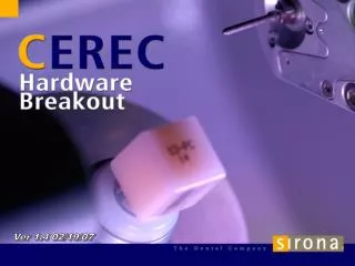
Ver 1.4 02/19/07
740 likes | 1.3k Views
Ver 1.4 02/19/07. MC XL Installation Requirements. Same power requirements as CEREC 3 Milling Unit Table must support 100 lbs To upgrade existing Customers, Acquisition unit needs Wireless LAN Card Kit Acquisition Unit PC min. must be “E” or higher

Ver 1.4 02/19/07
E N D
Presentation Transcript
MC XL Installation Requirements • Same power requirements as CEREC 3 Milling Unit • Table must support 100 lbs • To upgrade existing Customers, Acquisition unit needs Wireless LAN Card Kit • Acquisition Unit PC min. must be “E” or higher • For inLab, PC be “E” series equivalent and must have existing network card. All existing Patterson PC’s are compatible.
Engineering Features • Larger water tank, more mills before refills, switched timer interval, can’t run unit w/o filter, check valves prevents drips • Direct Drive motors, no gearboxes • Sealed chuck buttons • Roller bearings on shafts • Replaceable burr chucks, even with flush broken burrs • inLab has shaft bellows for high YZ usage • inLab has 4 motors, 2 burr sets, if a burr breaks on 1 set, unit continues on other set or load full contour and inlab burrs, sw will automatically pick correct burr set for restoration type. • User message display panel. No need to read message at Acq unit or PC. • Calibration Data stored on Milling unit, not Acq/PC • Automatic Downloads, no manual reset • Visual indication of XL status via of colored lights in chamber. • Wlan /Lan communication interface means more freedom to add units.
MC XL Setup 1. Water Tank • Water must be filled to the brim (A) • Tank capacity= 4 liters. Dentatec dose= 100ml
MC XL Setup 2. Install Drain Grid in bottom of chamber
MC XL Setup 3. Install Block Chuck • Screw on clockwise until a block cannot be inserted then turn counterclockwise until block slides in smoothly Old New Notch
MC XL Setup 4. Power connections • Plug in powercord (A) and turn rocker switch (B) on
MC XL Setup 5. Maintenance Mode • Turn on the MC XL (A) and press the “Pump” button (B) to prime the water system
MC XL Setup 6. TCP/IP Address • Press the “Config” button (A) to view MC XL TCP/IP Address. Note last number group based on S/N.
MC XL Setup 7. Rear Wireless Network Connection • Turn off MC XL • For WLAN (A), install jumper (typical installation)
MC XL Setup 8. Rear Network Connection (cont.) • For LAN direct cable connection, install cable in port marked “LAN” (B)
MC XL Setup 9. Acquisition Unit Direct Connection • Connect other end of network cable to lower port (A) on rear of Acquisition Unit
MC XL Setup 10. Install WLAN Card Kit in Acquisition Units w/o WLAN • Use enclosed instructions to disable Windows Firewall, install card and load/configure software
MC XL Setup 10. TCP/IP Overview • MC XL units use network connectivity for communication. • MC XL TCP/IP = 192.168.230.1XX • ACQ or PC TCP/IP = 192.168.230.2XX
MC XL Setup 10. TCP/IP Overview • ACQ or PC TCP/IP = 192.168.230.2XX • For multiple WLAN ACQ’s, TCP/IP address need to be unique. Last 3 digits must be changed on each ACQ unit.
MC XL Setup 10. TCP/IP Overview • To set up unique WLAN TCP/IP Address • Open Windows Control panel • Open Network Connections
MC XL Setup 10. TCP/IP Overview • To set up unique WLAN TCP/IP Address (cont.) • 3. Right click on Wireless Network Connection • 4. Click on Properties 3 4
MC XL Setup 10. TCP/IP Overview • To set up unique WLAN TCP/IP Address (cont.) • 5. Select Internet Protocol and click on Properties.
MC XL Setup 10. TCP/IP Overview • To set up unique WLAN TCP/IP Address (cont.) • 6. Change last 3 digits to a unique number between 201 and 254. • Then click OK • and reboot.
MC XL Setup 11. Load CEREC 3D V3.XX Software on Acq /PC • CEREC/inLab 3D V3.XX software required to operate MCXL units
MC XL Setup 12. Add Device in CEREC 3D Software • Turn on MC XL. * For WLAN units, turn on and configure one at a time, leave others off. • Bootup Acquisition Unit • Open CEREC 3D software
MC XL Setup 13. Add Device in CEREC 3D Software (cont.) • Click Yes to prompt for setting up milling unit • Label Milling Unit and click “Add” You are ready to mill!
MC XL Maintenance • Burr change • New chuck design with new tool • 2 turns to loosen • Tighten burr until click • Milling Unit Calibration • New calibration specimen and pins • Simular menu • Inlab requires both burr sets to be calibrated
MC XL Maintenance, Burrs • New burs: cylinder pointed bur 12.0 mm step bur12.0 mm for chairside materials and inceram cylinder pointed bur 20.0 mm step bur 20.0 mm for oxide ceramics such as YZ, inCORIS
MC XL Maintenance • Water change • New tank, double capacity • Requires 100ml of Dentatec • Approx 120min’s of milling before change message • Filter change interval TBD, maybe 100 milled units • Tank sensor
Adding Multiple XL Milling Units (Demo) • Max. 2 units per Acquisition Unit or PC. • Setup example • Connect WLAN Jumper on MC XL • Open CEREC 3D SW • Click on Settings>Configuration>Devices>Add Device Automatically and label. • Ready to Mill
Adding MC XL with a CEREC 3 Milling Unit (Demo) Can a MC XL be added with an existing CEREC 3 Milling Unit? Yes!
MC XL Internal Components • Removing Covers • Remove Water tank and open both front drawers • Remove both drawer Fronts (pull tabs and push down)
MC XL Internal Components Removing Covers (cont.) 3. Remove longer 3 screws from each side cover
MC XL Internal Components Removing Covers (cont.) 4. Remove shorter 4 screws from lower rear cover and pull off.
MC XL Internal Components Removing Covers (cont.) 5. Remove shorter 3 screws each side cover and 2 shorter screws from middle rear cover.
MC XL Internal Components Removing Covers (cont.) 6. Remove each side cover and rear middle cover. Caution! Right side cover with display panel has harness that needs to be disconnected before removingcompletely.
MC XL Internal Components • Air / Water Pump System • Water tank switch to reset water change message • On inLab, air pump also pressurizes bellows
MC XL Internal Components • Air Pump System • Pressurizes Mill Motors, shaft & (bellows inLab MC XL) (inLab shown)
MC XL Internal Components • Stepper Motors • w/ encoders determines position and torque
MC XL Internal Components • Direct Drive Milling Motor • w/ pressure transducer • 42,000 RPM • Replaceable burr chuck
MC XL Internal Components • Direct Drive Milling Motor Replacement (Step 1) • Remove 2 longer Housing screws “A” • Remove 2 shorter shaft screws “B”
MC XL Internal Components • Direct Drive Milling Motor Replacement (Step 2) • Use screw driver to separate housing • Caution! • Do not twist the housing or pull the rear housing out! • Gasket may be cut if screwdriver pushed in too far.
MC XL Internal Components • Direct Drive Milling Motor Replacement (Step 3) • Hold rear housing ”A” in place, Do Not Twist!, slowly pull out front housing and push motor at pushbutton chuck. • Caution! Disconnect motor harness “B”, then remove completely.
MC XL Internal Components • Direct Drive Milling Motor Replacement (Step 4) • Remove Motor from front housing (3 screws)
MC XL Internal Components • Direct Drive Milling Motor Replacement (Step 5) • Prior to installing new motor in front housing, verify o’ring is in place (A).
MC XL Internal Components • Direct Drive Milling Motor Replacement (Step 6) • Grease motor o’ring (A) and bend motor connector harness with connector red dot (B) towards motor body.
MC XL Internal Components • Direct Drive Milling Motor Replacement (Step 7) • Insert motor into front housing and align connector into plastic sleeve (A). Insert 3 mounting screws and tighten.
MC XL Internal Components • Direct Drive Milling Motor Replacement (Step 8) • Locate bridge connector (A) and insert onto chamber motor harness connector (B).
MC XL Internal Components • Direct Drive Milling Motor Replacement (Step 9) • Slightly grease rear motor seal (A) then slide front housing back on. Use needlenose to align and seat connectors as housing is pushed into place. Caution: Connector red dot to red dot!
MC XL Internal Components • Direct Drive Milling Motor Replacement (Step 10) • Align housings, insert long shaft screws (A) first and hand thread. Next insert short housing screws (B) and tighten. Finish by tightening shaft screws (A). Calibrate unit and test mill.
MC XL Internal Components • Spray Port Assembly • replaceable
MC XL Internal Components Milling Chamber, 4 mounting bolts
MC XL Internal Components Electronics – CCP Board • More efficiency, no heat sinks • Stores calibration data • To access, open right drawer, remove front drawer cover by pulling back tabs (arrows) and push cover down. Remove metal panel by loosening screw (A). Slide out board.
MC XL Internal Components Electronics – Power supply 48VDC