Download
1 / 16
160 likes | 185 Views
Follow these steps to efficiently replace the MC11000 sewing machine kit. Ensure a smooth transition while removing and installing components.

E N D
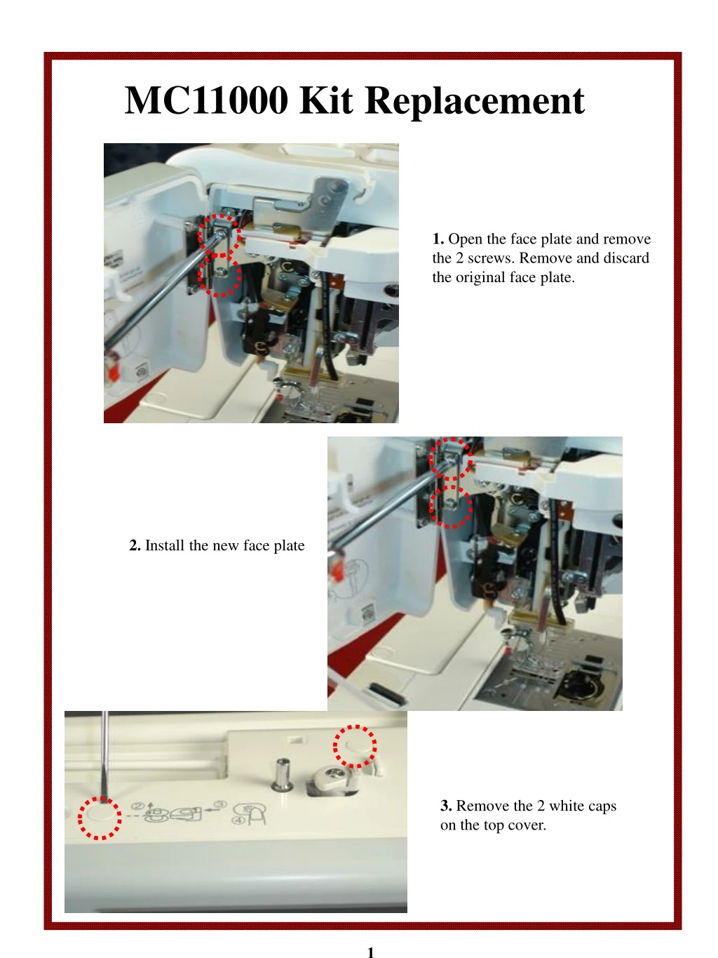
MC11000 Kit Replacement 1. Open the face plate and remove the 2 screws. Remove and discard the original face plate. 2. Install the new face plate 3. Remove the 2 white caps on the top cover. 1
MC11000 Kit Replacement 4. Remove the 2 screws on the top cover. 5. Lift the handle and remove the screw. 6. Gently start removing the top cover toward the back. Remove the presser dial knob. 2
MC11000 Kit Replacement 7. While holding the top cover, disconnect the bobbin winder motor cable. Remove the top cover. 8. Remove the 2 white caps on the belt cover. 9. Remove the 2 screws on the belt cover. 3
MC11000 Kit Replacement 10. Loosen the screw on the top. 11. Gently start to remove the belt cover. Make sure you release the locking tab on the bottom as you move the belt cover away. 12. Remove the belt cover. 4
MC11000 Kit Replacement 13. Open the face plate. Remove the screw and the thread arm guide. 14. Loosen the screw on the top and the screw on the bottom. 15. Loosen the screw (do not remove). 5
MC11000 Kit Replacement 16. Using a fine flat screwdriver, slightly push down the tip of the rear cover to release the locking tab. 17. As you start to remove the front cover, make sure to first push down on marked areas , and while holding down, start to pull toward you slowly. 18. Do not remove the front panel completely. Just pull 2-3 inches toward you. 6
MC11000 Kit Replacement 19. Remove the screw. Remove and discard the vertical thread arm guide. 20. Disconnect the two black and gray harness cables from the U board. Both cables belong to the tension unit. 21. Remove the larger screw that holds the bottom of the tension unit. 7
MC11000 Kit Replacement 22. Remove the screw that holds the upper part of the tension unit. 23. Gently remove the tension unit making sure not to damage the micro switch on the back. 24. Place the tension unit on a table and remove the 2 screws. Please be very careful when removing and installing the lower screw – as to not damage the sensor. 8
MC11000 Kit Replacement 25. Remove the black cushion from the old bracket and place it to the new bracket. ** Discard the old bracket. 26. Install the 2 screws making sure not to damage the sensor. 9
MC11000 Kit Replacement 27. Install the new thread guide and tighten the screw. 28. As you start to reinstall the tension unit, make sure your presser foot is down, and the vertical arm is to the right side of the tension unit arm. 29. Connect the 2 cables back to the circuit board. 10
MC11000 Kit Replacement 30. Install and tighten the upper screw. You may have to loosen this screw again if the tension unit does not line up with the top cover and front panel (See page16). 31. Install and tighten the screw. 32. Gently push the front panel toward the casting making sure not to pinch any wires. 11
MC11000 Kit Replacement 33. Before you tighten the lower screw, make sure the wires are away from the lower screw. Push the panel in and tighten the screw. Tighten the upper screw. 34. Install the thread guide and tighten the screw. 35. Tighten the screw. 12
MC11000 Kit Replacement 36. Install the presser dial knob. 37. While holding the top cover from the back, connect the bobbin winder motor cable. 38. Make sure the top cover locks into its groove in the front panel. The top cover should line up with the front panel. A minimum 2mm clearance should be between the front panel and tension bracket. Adjust if necessary. 2mm clearance 13
MC11000 Kit Replacement 39. Tighten the 2 screws on the top cover. 40. Lift the handle and tighten the screw. 41. Install the 2 white caps. 14
MC11000 Kit Replacement 42. Install the belt cover making sure the carriage release arm operates up and down freely. 43. Tighten the 2 screws. 44. Tighten the screw on the top. 15
MC11000 Kit Replacement 45. Install the 2 white caps. 47. If your front panel, tension unit and face plate are not lined up as shown here, make the necessary adjustments. 16