Download
1 / 36
390 likes | 637 Views
Introduction to Communication System: AM Radio Kit. ECE 002 Dr. Ahmadi Department of Electrical and Computer Engineering The George Washington University. Part I. Communication System and Amplitude Modulation. Communication System. Communication systems send information

E N D
Introduction to Communication System:AM Radio Kit ECE 002 Dr. Ahmadi Department of Electrical and Computer Engineering The George Washington University
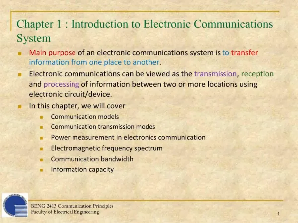
Communication System • Communication systems send information electronically over communication channels • Many different types of systems which convey many different types of information • Design challenges include hardware, system, and network issues • Communication systems recreate transmitted information at receiver with high fidelity
Communication System • Source encoder converts message into message signal or bits. • Transmitter converts message signal or bits into format appropriate for channel transmission (analog/digital signal). • Channel introduces distortion, noise, and interference. • Receiver processes received signal back to message signal. • Source decoder decodes message signal back into original message. Source Encoder Transmitter Signal Channel Receiver Source Decoder
Amplitude Modulation(AM) • Modulation: • The process of converting a signal so that it can be successfully sent through a medium. • The addition of the original signal to a carrier signal • Types of Modulation: • Analog Modulation – AM,FM, etc • Digital Modulation • History: 1900s AM invented and popularized by De Forest; commercial radio station begins broadcasting in Pittsburgh 1920.
Amplitude Modulation(AM) • AM works by varying the amplitude of the transmitted signal in relation to the information being sent. For example, changes in the signal amplitude can be used to reflect the sounds to be reproduced by a speaker • Audio signal - fa • Carrier signal - fc
Receiver: AM Radio Kit • Model: AM-780 • A standard AM radio frequency receiver • Radio frequency (RF): 3kHz – 300GHz • AM Broadcast Frequencies : 535kHz – 1605kHz
AM Radio: 535kHz – 1605kHz FM Radio: 88MHz – 108MHz
AM-780 Block Diagram Component List: • Printed Circuit Board(PCB) • (mechanically support and electrically connect electronic components) • LC Circuit: Inductors and Capacitors. • (Selects the input signals by different frequencies) • IC 484: Transistor. • (Amplifies the selected input signal) • Peak Detector: Two diodes. • (Detects the peak of the amplified input signal) • IC LM-386 chip: Power amplifier • Specifications: http://www.national.com/mpf/LM/LM386.html#Overview • Antenna, Speaker, Resistors/Potentiometers and Wires Antenna LC Circuit Transistor (IC 484) Diodes IC LM 386 Chip
Circuit Board • Printed Circuit Board
Resistors • Use bands to tell resistors apart and to find value
Capacitor • An electronic component that has ability to store a charge and block DC current.
Semiconductors Diodes Transistor 484 Integrated Circuits IC 386
SolderingSafety Precautions : • Never touch the element or tip of the soldering iron.They are very hot (about 400°C) and will give you a nasty burn. • Take great care to avoid touching the mains flex with the tip of the iron.The iron should have a heatproof flex for extra protection. An ordinary plastic flex will melt immediately if touched by a hot iron and there is a serious risk of burns and electric shock. • Always return the soldering iron to its stand when not in use.Never put it down on your workbench, even for a moment! • Work in a well-ventilated area.The smoke formed as you melt solder is mostly from the flux and quite irritating. Avoid breathing it by keeping you head to the side of, not above, your work. • Wash your hands after using solder.Solder contains lead which is a poisonous metal.
Preparing the soldering iron: • Place the soldering iron in its stand and plug in.The iron will take a few minutes to reach its operating temperature of about 400°C. • Dampen the sponge in the stand.The best way to do this is to lift it out the stand and hold it under a cold tap for a moment, then squeeze to remove excess water. It should be damp, not dripping wet. • Wait a few minutes for the soldering iron to warm up.You can check if it is ready by trying to melt a little solder on the tip. • Wipe the tip of the iron on the damp sponge.This will clean the tip. • Melt a little solder on the tip of the iron.This is called 'tinning' and it will help the heat to flow from the iron's tip to the joint. It only needs to be done when you plug in the iron, and occasionally while soldering if you need to wipe the tip clean on the sponge.
Start soldering: • Hold the soldering iron like a pen, near the base of the handle.Imagine you are going to write your name! Remember to never touch the hot element or tip. • Touch the soldering iron onto the joint to be made.Make sure it touches both the component lead and the track. Hold the tip there for a few seconds and... • Feed a little solder onto the joint.It should flow smoothly onto the lead and track to form a volcano shape as shown in the diagram. Apply the solder to the joint, not the iron. • Remove the solder, then the iron, while keeping the joint still.Allow the joint a few seconds to cool before you move the circuit board. • Inspect the joint closely.It should look shiny and have a 'volcano' shape. If not, you will need to reheat it and feed in a little more solder. This time ensure that both the lead and track are heated fully before applying solder.
Start soldering: Resistor 1
Soldering Tips: • Ensure that items to be soldered are perfectly clean. This can be achieved with wire wood or fine emery cloth. Just because a piece of metal looks bright and clean it may not be. • Make a good mechanical connection by wrapping wires around each other or around a terminal. • When applying heat, do not apply it to the solder. Heat the base material, e.g. wires so they become sufficiently hot to melt the solder and flow it into the joint. A small amount of fresh solder on the tip when you begin soldering will help to carry heat from the iron to the joint. • When solder has been applied to a joint smoothly slide the iron away to leave the joint neat. • Avoid moving joint or wire after removing iron. Blowing on the joint will speed cooling. • On electrical and electronic components avoid too much heat. A heat sink can be used to dissipate heat away from the component. • Do not apply more solder than needed. Excess solder can cause short circuits. • It is advisable to pre tin components before soldering, especially stranded wire. Twist the strands together, then heat and saturate with solder. • Sweating a joint is easy after tinning. Just twist wires together and apply heat. • To desolder a joint apply heat and use a soldering aid like solder wick to remove solder and separate joint. Be sure to use new solder when re-soldering. • Fumes from some fluxes can be unpleasant so be sure there is good ventilation in the work area. • Do not use a file to clean soldering tip, wiping on a wet sponge when tip is hot should keep tip clean.