Download
1 / 32
320 likes | 341 Views
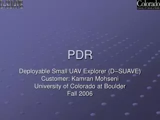
Team “Canard” October 12th, 2006. Structures 1 PDR. 9.3 deg. 0.89ft. S wing = 4.16 ft 2. 0.3. balsa. Easy to built Good surface. Expanded polystyrene. Wing Sizing. Aerodynamics gives the geometry Load case : Resist to 10g (74ft radius at 100mph) Materials. MH 43. 0.4 ft.

E N D
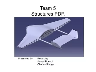
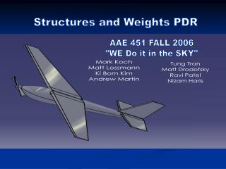
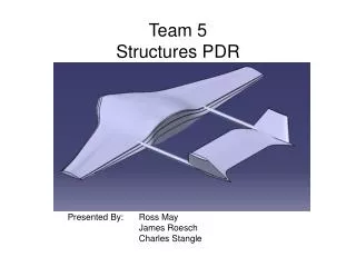
Team “Canard” October 12th, 2006 Structures 1 PDR
9.3 deg 0.89ft Swing = 4.16 ft2 0.3 balsa Easy to built Good surface Expanded polystyrene Wing Sizing • Aerodynamics gives the geometry • Load case: Resist to 10g (74ft radius at 100mph) • Materials MH 43 0.4 ft Thickness:8.5% Wing should support 50 lb With a weight of 5 lb AAE 451 Team 1
Proof of n value AAE 451 Team 1
Quarter chord MAC: application of the lift Sizing Method • Discretization of the wing • Determination of the loads 1 2 3 4 • For each part, we can figure out: • The bending moment due to the lift • The torsion torque due to the aerodynamic moment AAE 451 Team 1
Distribution of Lift The lift is assumed to be linear: Lift = Wloading x Surface AAE 451 Team 1
Bending Moment L1 L2 M=L1.d1 + L2.d2 + ….. d1 MAC d2 AAE 451 Team 1
b a Minimal thickness • Assumptions: • Only bending loading • Foam doesn’t carry the load • The balsa should resist the load • We assume the shape of the airfoil is an ellipse t is figured out from IG polar inertia AAE 451 Team 1
Skin Thickness Easy to built, but 70% heavier than discretized thickness 1.53 in Optimal thickness distribution AAE 451 Team 1
Twist and Deflection • Twist • Assumption: Only the aerodynamic twist (twist due to the swept angle is neglected) • Deflection =100 mph y y’ Lift at MAC y’ with Thales theorem AAE 451 Team 1
Twist max. twist: 0.7° AAE 451 Team 1
Deflection 0.21 in AAE 451 Team 1
Carbon Spar Advantages The minimum skin thickness is too thick to bend around the airfoil shape (from experience) Method: Assume iso-rigidity for the carbon tube and the skin (EI)skin=(EI)spar 50% of the load in the spar 50% of the load in the skin Redo the calculations for the skin with 50% of load AAE 451 Team 1
Skin Thickness With Spar From this point, the structure resist without spar Cut spar at 1.50ft AAE 451 Team 1
Skin Thickness Balsa sheet thickness t = 0.06 in ($22 for 253”x36”x1/16”) 4.8 in ID ≈ 0.32 in OD ≈ 0.45 in Thickness ≈ 0.13 in Final size will depend on market availability AAE 451 Team 1
CG Estimation/Spar Location Mean Aero. Chord (MAC) Spar Length = 3.0 ft (≈1/2 of wingspan) CG Location: 33% of Mean Aerodynamic Chord AAE 451 Team 1
0.38 ft 0.07 ft 1.84 ft Horizontal tail structure • Geometry • Structure layout: • Full sheet of balsa sanded • Foam + balsa skin NACA 0006, 6% thickness ratio AAE 451 Team 1
Wing downwash = -0.00507 Wing AOA = -0.0997 Incidence of the Htail =0 Control surface deflection 20° = -0.125 Horizontal tail calculations Load case: High speed dash + 20° deflection L=0.5ρSV2CL From control team we have: V is the most influent parameter for the Lift force AAE 451 Team 1
b a Bending moment MAC location y x root tip Lift Results: Min. thickness: 2.18e-2 in Very thin, impossible to find in the market Total deflection: 5.3e-1 in AAE 451 Team 1
Final tail structure layout • Horizontal tail: Foam core + 0.06 in balsa sheet (similar to the wing) • Vertical tail: The final geometry is not define yet We plan to make it in a full sheet of balsa sanded. AAE 451 Team 1
Component CG Table Components more difficult to vary Components easy to vary Components that cannot be varied Green Components need to be moved until this value = 0 AAE 451 Team 1
Graphical Representation of Weight Distribution AAE 451 Team 1
Working Model AAE 451 Team 1
Components Layout GearBox S.C. Battery Payload Motor AAE 451 Team 1
V-n Diagram Trade Study on n-loading, turn radius, and speed will provide more technical justification CLMAX = 0.9 S = 4.15 ft2 m = 5 lbs Gmax = 10 VDive = 1.3*VCruise VStall ≈ 35 ft/s -5 g’s (from Raymer Table) VCruise = 115 ft/s AAE 451 Team 1
Landing Gear • Roskam method for landing gear sizing: 1. Landing gear system: Fixed 2. Landing gear configuration: taildragger 3. Locate c.g.: 1.23 ft from the nose 4. Decide preliminary landing gear Goldberg Landing Gear: Glass filled Length: 14-3/8” (from axle to axle) Mount area length: 3-7/16” Height: 4-1/2” AAE 451 Team 1
Landing Gear 5. Longitudinal tip-over analysis 15 deg 12 deg 6. Lateral tip-over analysis Ψ≤ 55 deg Main gear Tail gear AAE 451 Team 1
Landing Gear 7. Ground clearance criteria 8. Max. static load per strut > 5 deg WTO = Total weight = 5.0 lbs nS = Number of main gear struts = 2 Pm = Main gear load Pt = Tail gear load lm = distance from main gear to c.g. = 1.6” lt = distance from tail gear from c.g. = 2.55” WTO nSPm Pt lm lt Pt = (WTOlm)/(lm+lt) = 1.93 lbs Pm = (WTOlt)/nS(lm+lt) = 1.54 lbs lm+lt AAE 451 Team 1
Landing Gear 9. Number of wheels: 2 for main gear 1 for tail gear Hayes Racing Wheels: • Glassfilled Nylon • Lightweight • Width: .177’’ • Diameter: 2.25” OD Ohio Tail Wheel Tiny 4-8 lbs AAE 451 Team 1
Wing-Fuselage Attachment Wing top view Fuselage Rib Lmax/4 Nylon screw Carbon rod AAE 451 Team 1
Lmax/4 Lmax/4 Wing-Fuselage Attachment Nylon screws from hobby lobby: D = .23622 in Length = 1.9685 in Cross-sectional area: A = π(D/2)2 = .043825 in2 F = n*W/4 = 12.5 lbs n= number of g σ = F/A= 12.5 lbs/ .043825 in2 = 285.22 psi Ultimate Tensile Strength for Nylon = 10152.6 psi Margin = 34 Margin=σmax/ σ-1 AAE 451 Team 1
Lmax/4 Wing-Fuselage Attachment Front view Carbon rod: D= .23622 in t = thickness of rib = .23622 in σ = F/(D*t) = 12.5 lbs/((.23622 in)(.23622 in)) = 224.015 psi Ultimate Compressive Strength of balsa = 725.2 psi Margin = 2.2 Carbon rod t Top view AAE 451 Team 1
Questions AAE 451 Team 1


![Data Structures [1]](https://cdn3.slideserve.com/6547756/data-structures-1-dt.jpg)