Download

1 / 19
190 likes | 313 Views
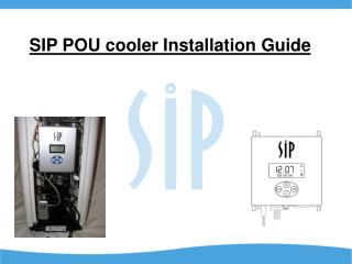
SIP POU cooler Installation Guide. Getting Started. The SIP 2000 can be easily installed in most POU coolers in just a few minutes. The tools needed are a drill, a 3/16” and a ¼” drill bit, a screw driver or nut driver to remove the cabinet screws, and a small pair of diagonal cutting pliers.

E N D
Getting Started The SIP 2000 can be easily installed in most POU coolers in just a few minutes. The tools needed are a drill, a 3/16” and a ¼” drill bit, a screw driver or nut driver to remove the cabinet screws, and a small pair of diagonal cutting pliers.
Unpacking the SIP 2000 The SIP 2000 comes packaged like this. And inside you will find the SIP 2000 and everything needed for a professional installation.
Here is what comes in the package Air Filter Air diffuser Air Hose Insulation Foam Down Tube Main Unit Test Button and Harness Air Pump Cooler Patch Cord Power CordExternal Indicator Light Zip Ties Spare Fuse Note: not all parts are used in many installations and included parts may vary in appearance.
Optional Feature (if not using skip to slide 10) Install the Service Light In order to install the external indicator light the cabinet must be removed After removing the cabinet locate where you want to install the service light. We are going to install our light in the front, top, center of the cabinet Drill a 3/16” hole where the External indicator light will be installed
Press light into hole being careful not to break the wires Be sure to remove any burrs from the hole. External Indicator Light Installation Make sure the light is firmly inserted and protrudes from the front of the cabinet The installed light should look like this
Now is the time to install the Service Light guide label. Place over the External Indicator Light on the outside of the cabinet. The external indicator light goes here
Now replace the cabinet. Be careful not to pinch the external indicator light wire.
Locating the Down Rod Most POU coolers have an in-reservoir float system that is covered with a bonnet like this model. Careful thought must be given to the placement of the downrod. The downrod must not interfere with the float action and must fit under the bonnet. Additionally the baffle may need to be notched in order to accommodate the downrod reaching the bottom of the reservoir. Our placement will be at the back of the float plate. Be certain that the Downrod will not interfere with float. The manufacturer has already notched the baffle for us.
Installing the Downrod Drill a 3/16” hole and remove any burrs that the drill left behind. Locate the spot where the downrod will enter the reservoir. Make sure the silicone grommet is fully inserted into the hole. Insert silicone grommet from the top of the float plate into the new hole.
Installing the Downrod Push Downrod 90° elbow meets Grommet Insert Downrod through Grommet The completed Downrod should look like this Attach Air Diffuser to Downrod using a 1” section of Tubing.
Installing the Downrod Install finished assembly into reservoir making sure to line up Downrod in baffle Downrod may need to be adjusted up or down in order to position air diffuser near bottom of reservoir. Downrod installed
Installing Check Valve & Air Filter The check valve must be installed with the air flow pointing away from the main unit and toward the reservoir. Cut a 5” section of hose and attach it to downrod as shown. Attach other end of downrod hose to the top of the check valve Attach the remaining long section of hose to the bottom of the check valve. The air filter can be placed in-line between the air pump and the SIP unit or it can be positioned in-line between the SIP unit and the check valve . (servicing convenience would determine location)
Finishing Up Now it’s time to mount the Main Control Box. Us the supplied zip ties to secure unit to the condenser. Remember to leave access to other cooler components such as the hot tank on / off switch and the cold thermostat. Attach the loose hose from the check valve to the top outlet of the Main Control Box. Attach hose from Air Pump outlet to bottom inlet of Main Control Box. Mount Air Pump above or below the Main Control Box using zip ties provided. Air filter can be located in-line between air pump and Main Control Box
Finishing Up Use this diagram to connect all cords and plugs
Finishing Up Use remaining zip ties to secure hoses and cords. One last check to make sure everything is properly connected. Now is a good time to use the test button to make sure all components are operational.
For More Information Contact SIP Technologies LLC 72070 Hwy 1077 Covington, LA 70433-0851 (800) 655-4635 (302) 655-6300 www.siptechnologies.com