Download
1 / 68
690 likes | 891 Views
Analysis Methods for Skewed Structures. 3D Finite Element Model. Analysis Types:. Refined model. Crossframe Effects Ignored. Crossframe Effects Included. Grid model (Model Crossframes w/ beams) MDX Grid DESCUS Grid model (Model Crossframes w/trusses) Finite Element

E N D
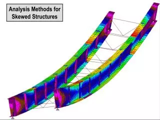
Analysis Methods for Skewed Structures 3D Finite Element Model
Analysis Types: Refined model Crossframe Effects Ignored Crossframe Effects Included • Grid model (Model Crossframes w/ beams) MDX Grid DESCUS • Grid model (Model Crossframes w/trusses) Finite Element • 3D Finite Element model BSDI Finite Element • Line girder model MDX Merlin Dash BSDI StlBridge PC-BARS Others…
Mz Line Girder Model • Most commonly used method for non-complex structures (MDX, Merlin Dash) • Each girder is modeled independently, with crossframe effects ignored • Cannot predict skew effects • Should not be used on structures where skew effects are expected to be significant
Refined Model:Grid model using crossframe beam elements • All girders and crossframes are included in one model. • Both girders and crossframes are modeled using beam elements. • A standard beam element cannot accurately duplicate crossframe stiffness, so crossframe stiffness in the model is approximate. • DESCUS and MDX Grid use variations of this method.
Refined Model:Grid model using crossframe truss elements • All girders and crossframes are included in one model. • Girders are modeled as linear beam elements. • Crossframes are modeled using truss elements. • Crossframe stiffness can be more accurately modeled than with the beam element model.
Refined Model:Three dimensional finite element model • Girder flanges, webs, and stiffeners are modeled as plate elements. • Crossframe members are modeled as truss elements. • Most complex model (of those compared) • Most accurately reflects actual behavior
Model Capabilities: * Girder warping stiffness can be approximated in these models.
Analyses: Parametric Study: Study of single span structures with variable skews and span lengths. Structures:
Structure 6: FRAMING PLAN TRANSVERSE SECTION
Study Conclusions: • For all the bridges studied, results from conventional gird analysis (with beam element crossframes) was sufficiently accurate when considering intermediate crossframe effects. • Differences in crossframe stiffness do produce differences in results between the different methods, but these differences were small in the cases investigated. • Truss element crossframes are needed to properly account for end crossframe effects, but these effects do not occur if the end crossframe is not fully connected during the deck pour. • For complex structures, higher levels of analysis should be considered in order to obtain accurate results.
Analysis of Lean-on Construction: • Evaluate girder forces using a global model • Determine if stiffness of bracing is adequate • Determine if strength of bracing is adequate Multiple steps are required to analyze a lean-on system:
Evaluating Girder Forces, External Lean-on Systems: • An external lean-on system is a system where no bracing is fully connected in the portion of the structure that will be loaded. • Lean-on systems that are braced externally only (no girders receiving deck load are directly connected using crossframes) can be analyzed using line-girder analysis. External Lean-on
Evaluating Girder Forces, Internal Lean-on Systems: • An internal lean-on system has both crossframes and lean-on braces within the area being loaded. • A refined analysis must be used to accurately model the behavior of an internal lean-on system. Internal Lean-on
Conventional Crossframe Stiffness Matrix: • Conventional crossframes restrain both differential deflection and differential twist between adjacent girders.
Lean-on Brace Stiffness Matrix: • Lean-on braces restrain differential twist, but not differential deflection.
Internal Lean-on System model: • Not all packaged analysis software is capable of accurately modeling the behavior of a lean-on brace. • Lean on braces can be modeled by creating a grid model using finite element software. Internal Lean-on
Internal Lean-on System model: • Diagonal members can be installed at the lean-on brace locations after the deck pour is complete. • A separate model will need to be created to model the structure after the crossframes are fully connected. Stage 1 Model Stage 2 Model
Lean on System: Strength and Stiffness of Girder Bracing Calculations need to be performed to show that the strength and stiffness of each line of lateral bracing is adequate. • When I-beams are loaded, out of plane forces are generated due to initial imperfections in the orientation of the structure. • If these out-of-plane forces exceed the capacity of the bracing, failure of the bracing members can occur. • If deflections due to these forces become large, buckling of the girders can occur.
Lean on Sytem: Bracing Strength • Each girder generates a lateral force F that can be calculated using the following equation: L = Beam Span Mu = Factored Moment at Bracing Location n = Number of Braces in Girder Span Lb = Spacing Between Torsional Braces hb = Depth of Beam Cb = Moment Gradient Factor Iy = Moment of inertia for lateral bending • For design purposes, the lateral force from each girder will be assumed to act in the same direction.
Lean on System: Bracing Strength • Other lateral forces, such as forces due to the overhang bracket and forces produced when the deck load is added, may act in conjunction with the lateral force F. • All relevant service forces should be included when the capacity of the bracing members is checked.
Lean-on System: Bracing Stiffness • If the deflection due to lateral forces becomes too large, lateral torsional buckling of the beams can occur. • A minimum level of stiffness must be obtained for each line of bracing in order to ensure that buckling does not occur. bsys = Total system stiffness bT = Minimum Required Stiffness
Lean-on System: Bracing Stiffness • The compression flange of the girder can be thought of as a column supported by spring supports at each crossframe location. • If the stiffness of the supports is below a minimum stiffness (k), the column buckles.
Calculation of bracing stiffness required: • The minimum required stiffness can be calculated based on the compressive force in the girders, which is proportional to the girder moment. • bT in the equation below represents the required stiffness for a line of crossframes. L = Span Length Mu = Factored Moment at Bracing Location n = Number of Braces in Girder Span E = Modulus of Elasticity Iy = Weak Axis Moment of Inertia Cb = Moment Gradient Factor
Calculation of bracing stiffness provided: • The total system stiffness for a braced system is dependent on the stiffness of the braces and the cross-sectional stiffness of the girders. • Both the in-plane torsional stiffness and the warping stiffness of the girder should be considered. bsys = Total system stiffness bb = Brace Stiffness bsec = Cross-sectional girder distortion bg = In-plane girder stiffness
Bracing Stiffness: • bb accounts for stiffness of the bracing. • Different formulas are used for different types of crossframes and diaphragms. • The formula presented here is for an ODOT standard X-brace. bb = In-plane girder stiffness Ld = Length of Diagonal ngc = Number of girders per crossframe E = Modulus of elasticity s = Girder spacing hb =Height of girder Ad = Cross-sectional area of diagonal As = Cross-sectional area of strut
In-plane girder stiffness: • bg accounts for the strong-axis stiffness of the girders resisting global twisting of the bridge section. bg= In-plane girder stiffness L = Span length ng= Number of girders E = Modulus of elasticity Ix = Strong axis moment of inertia s = Girder spacing
Cross Sectional Grider Distortion: • bsec accounts for stiffness of the girder web at the bracing connection bsec= Cross-sectional girder distortion h= Distance between flange centroids N= Contact length for torsional brace E= Modulus of elasticity tw= thickness of web ts = thickness of stiffener bs= width of stiffener Web distortion allows girders to twist
Bracing Stiffness Summary: System stiffness must be greater than minimum required stiffness: Calculate system stiffness & required stiffness: Calculate system stiffness components:
Lean on System: Strength and Stiffness of Girder Bracing A complete explanation of lean-on bracing design is beyond the scope of this presentation. The following references provide guidance on this topic: Herman, Helwig, Holt, Medlock, Romage, and Zhou, “Lean-on Crossframe Bracing for Steel Girders with Skewed Supports” http://www.steelbridges.org/pdfs/.%5CHerman.pdf Beckmann and Medlock, “Skewed Bridges and Grider Movements Due to Rotations and Differential Deflections” http://www.steelbridges.org/pdfs/.%5CBeckmann.pdf Yura, J. A. (2001), “Fundamentals of Beam Bracing”, Engineering Journal, American Institute of Steel Construction, 1st Quarter, pp. 11-26.
Summary of Lean-on System Design: • Perform line girder analysis to determine moments and shears due to girder self weight. • Perform grid analysis using non-composite section properties and top and bottom strut braces at appropriate locations to determine moments and shears due to the deck weight. • Perform grid analysis using composite section properties and fully connected crossframes to determine moments and shears due to superimposed dead load and live load. • Calculate bracing forces occuring during the deck pour to verify that member capacity is adequate. • Calculate required stiffness and provided stiffness for each line of bracing during the deck pour to verify that adequate bracing is provided.
Design Example: • Single span • 5 girder lines • 150 ft span • 60 degree skew
Design Example Continued: Preliminary girder elevation: • Initial girder size is determined using line girder analysis. • In the final design, all girders should meet line girder design requirements at a minimum. Do not reduce the strength of the girders based on refined analysis results.
30° < Skew ≤ 45° Skewed Bridge Design Process Design Example Skew > 45° Perform Line Girder Analysis Differential Deflections < S/100 Differential Deflections < S/100 Perform Refined Analysis* Stiffen Design: 0% to ± 25% Additional Steel No No Yes Yes Girder Twist < 1/8”/ft? Girder Twist < 1/8”/ft? No Stiffen Design: 0% to ± 25% Additional Steel Design Using Line Girder Analysis No Yes Yes Check That Design Rates Using PC-BARS Implement Internal Lean-on Bracing with Refined Analysis* Finish Design Using Refined Analysis: Erect Girders Vertical And Allow To Rotate Girder Twist < 1/8”/ft? No Yes Check That Design Rates Using PC-BARS Implement External Lean-on Bracing*
30° < Skew ≤ 45° Skewed Bridge Design Process Design Example Skew > 45° Perform Line Girder Analysis Differential Deflections < S/100 Differential Deflections < S/100 Perform Refined Analysis* Stiffen Design: 0% to ± 25% Additional Steel No No Yes Yes Girder Twist < 1/8”/ft? Girder Twist < 1/8”/ft? No Stiffen Design: 0% to ± 25% Additional Steel Design Using Line Girder Analysis No Yes Yes Check That Design Rates Using PC-BARS Implement Internal Lean-on Bracing with Refined Analysis* Finish Design Using Refined Analysis: Erect Girders Vertical And Allow To Rotate Girder Twist < 1/8”/ft? No Yes Check That Design Rates Using PC-BARS Implement External Lean-on Bracing*
Perform Refined Analysis* Refined Model: • The initial model is for the deck pour case only. • Non-composite section properties should be used. • A grid model with truss-element crossframes is used in this case. • End crossframes are not included because they will not be connected during the deck pour.
Perform Refined Analysis* Refined Model, Crossframe Members: Truss Elements Rigid Elements Beam Element • Crossframes members are modeled using truss elements. • Rigid elements are used to represent stiffener connections to girders. • This is one possible method. Other methods can be used to achieve the same result.
30° < Skew ≤ 45° Skewed Bridge Design Process Design Example Skew > 45° Perform Line Girder Analysis Differential Deflections < S/100 Differential Deflections < S/100 Perform Refined Analysis* Stiffen Design: 0% to ± 25% Additional Steel No No Yes Yes Girder Twist < 1/8”/ft? Girder Twist < 1/8”/ft? No Stiffen Design: 0% to ± 25% Additional Steel Design Using Line Girder Analysis No Yes Yes Check That Design Rates Using PC-BARS Implement Internal Lean-on Bracing with Refined Analysis* Finish Design Using Refined Analysis: Erect Girders Vertical And Allow To Rotate Girder Twist < 1/8”/ft? No Yes Check That Design Rates Using PC-BARS Implement External Lean-on Bracing*
Girder Twist < 1/8”/ft? Output from refined model: • The highest twists occur at the girder end in this case. Twists along the full length of each girder should be investigated. • Maximum girder twist = 0.94° • Tan(0.94°) x 12” = 3/16” per foot 3/16” per foot > 1/8” per foot Twist is outside of acceptable range
30° < Skew ≤ 45° Skewed Bridge Design Process Design Example Skew > 45° Perform Line Girder Analysis Differential Deflections < S/100 Differential Deflections < S/100 Perform Refined Analysis* Stiffen Design: 0% to ± 25% Additional Steel No No Yes Yes Girder Twist < 1/8”/ft? No Girder Twist < 1/8”/ft? Stiffen Design: 0% to ± 25% Additional Steel Design Using Line Girder Analysis No Yes Yes Check That Design Rates Using PC-BARS Implement Internal Lean-on Bracing with Refined Analysis* Finish Design Using Refined Analysis: Erect Girders Vertical And Allow To Rotate Girder Twist < 1/8”/ft? No Yes Check That Design Rates Using PC-BARS Implement External Lean-on Bracing*
Stiffen Design: 0% to ± 25% Additional Steel Original Design: Girder Weight = 54.0 kips Stiffened Design: Girder Weight = 67.4 kips (25% increase) • Increasing girder stiffness reduces deflection and rotations. • In this case, web depth cannot be increased due to site constraints.
30° < Skew ≤ 45° Skewed Bridge Design Process Design Example Skew > 45° Perform Line Girder Analysis Differential Deflections < S/100 Differential Deflections < S/100 Perform Refined Analysis* Stiffen Design: 0% to ± 25% Additional Steel No No Yes Yes Girder Twist < 1/8”/ft? Girder Twist < 1/8”/ft? No Stiffen Design: 0% to ± 25% Additional Steel Design Using Line Girder Analysis No Yes Yes Check That Design Rates Using PC-BARS Implement Internal Lean-on Bracing with Refined Analysis* Finish Design Using Refined Analysis: Erect Girders Vertical And Allow To Rotate Girder Twist < 1/8”/ft? No Yes Check That Design Rates Using PC-BARS Implement External Lean-on Bracing*
Girder Twist < 1/8”/ft? Girder twist after 25% increase in steel weight: • Maximum girder twist = 0.76° • Tan(0.76°) x 12” = 5/32” per foot 5/32” per foot > 1/8” per foot Twist is still outside of acceptable range
30° < Skew ≤ 45° Skewed Bridge Design Process Design Example Skew > 45° Perform Line Girder Analysis Differential Deflections < S/100 Differential Deflections < S/100 Perform Refined Analysis* Stiffen Design: 0% to ± 25% Additional Steel No No Yes Yes Girder Twist < 1/8”/ft? Girder Twist < 1/8”/ft? No No Stiffen Design: 0% to ± 25% Additional Steel Design Using Line Girder Analysis Yes Yes Check That Design Rates Using PC-BARS Implement Internal Lean-on Bracing with Refined Analysis* Finish Design Using Refined Analysis: Erect Girders Vertical And Allow To Rotate Girder Twist < 1/8”/ft? No Yes Check That Design Rates Using PC-BARS Implement External Lean-on Bracing*
Implement Internal Lean-on Bracing with Refined Analysis* Differential deflections calculated using grid analysis: • Lean-on designs reduce girder twist by temporarily replacing crossframes where large differential deflections occur with braces consisting of top and bottom struts only. • In an internal lean-on design, some crossframes are left in place during the deck pour while others are replaced. • Mapping crossframe differential deflections is helpful in determining which crossframes should be left in place. (Using original girder design)
(Unstiffened Model) Bracing layout: Implement Internal Lean-on Bracing with Refined Analysis* Differential deflections calculated using grid analysis: