Download
1 / 1
50 likes | 260 Views
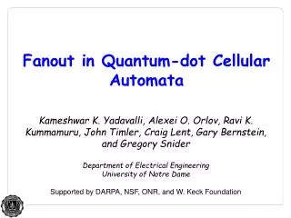
Northeastern U N I V E R S I T Y. A. B. F. C. A. F. B. MV. C. Inverter. Quantum dot. electron. 1. 0. Binary ‘1’. Binary ‘0’. Electrical and Computer Engr. Department. Rui Tang, Fengming Zhang, Yong-Bin Kim

E N D
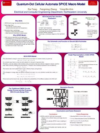
Northeastern U N I V E R S I T Y A B F C A F B MV C Inverter Quantum dot electron 1 0 Binary ‘1’ Binary ‘0’ Electrical and Computer Engr. Department Rui Tang, Fengming Zhang, Yong-Bin Kim Electrical and Computer Engineering Department, Northeastern University • Why QCA: • CMOS technology has reached physical limits • Technology Goal • » The cell size of QCA is about • several nanometers @ room temperature • Alternative Nano technology: • » Quantum Cellular Automata (QCA) • » New method of information transformation • Why SPICE Model: • CAD tools are essential for real application • » QCADesigner is a good bottom-up design tool. • » Traditional CMOS design flow is a top-down design flow. • » Using conventional, commercial CMOS circuits design • tools is possible and convenient for QCA circuits design. • » To use SPICE to simulate QCA circuits, we have to build • the behavioral model of QCA cells QCA Cell and Two-Junction Realization Majority Voter (MV): F=AB+AC+BC Quantum-Dot Cellular Automata SPICE Macro Model device cell • 4 “dots” and 2 electrons • Electrons tend to occupy antipodal dots • (a) shows two-junction realization of the quantum cellular automata • (b) shows a schematic diagram of the half-QCA cell • AND/OR functions obtained by setting one input of MV to: • 0 for AND • 1 for OR The Schematic and Function of One-bit QCA Full-Adder Graph Representation of QCA SPICE Model QCA SPICE Model • The electrostatic energy to move an electron from one island i to another island j is given by: • In a simple case, there is only one extra electron in one pair of quantum dots. • Therefore, only two states of the transition exist, one state is the extra electron trapped in island i and the other state is island j holding the extra electron. Therefore, the following expression can be obtained: • The tunnel rate is formulated based on the orthodox theory and given by: • The changes in energy when an electron tunnels from node i to j or an electron tunnels from node j to i are: • Once we know the tunnel rate, we can deduce the probabilities of the different states in the QCA cell: • Cin is the capacitance between the QCA cells • Ci is the capacitance between the two pairs of QCA dots • RT1 is the junction resistor Simulation Results The Traditional CMOS Circuits Design Process and the Proposed QCA Circuits Design Flow Truth Table of Full Adder Conclusions and Future Research Conclusions Future Researches • SPICE model for QCA cell is proposed: • Based on the orthodox theory and single electron tunneling • First effort to develop SPICE macro modeling of QCA cells • Based on experimental demonstrations of QCA cells • The functions of full-adder and majority voter are verified in SPICE • Develop QCA Synthesis Methodology • Timing Characterization Across QCA Modules • Cell Placement/Routing for Room • Temperature Operation • PipelineDesign for High Performance