Download
1 / 34
360 likes | 390 Views
Learn about the dominance of Ethernet in LANs, IEEE standards, LLC and MAC sublayers, Ethernet evolution, addressing formats, and types of transmission.

E N D
Wired Local Area Network (Ethernet-IEEE 802.3) B. R. Chandavarkar CSE Dept., NITK, Surathkal brcnitk@gmail.com
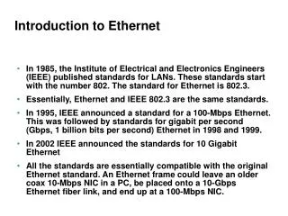
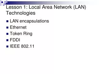
The LAN market has seen several technologies such as Ethernet, Token Ring, Token Bus, FDDI (Fiber Distribution Data Interface), and ATM LAN. • Some of these technologies survived for a while, but Ethernet is by far the dominant technology. • In this chapter, we first briefly discuss the IEEE Standard Project 802, designed to regulate the manufacturing and interconnectivity between different LANs. We then concentrate on the Ethernet LANs. IEEE Standards • In 1985, the Computer Society of the IEEE started a project, called Project 802, to set standards to enable intercommunication among equipment from a variety of manufacturers. • Project 802 does not seek to replace any part of the OSI or the Internet model. Instead, it is a way of specifying functions of the physical layer and the data link layer of major LAN protocols. • In 1987, the International Organization for Standardization (ISO) also approved it as an international standard under the designation ISO 8802. • The IEEE has subdivided the data-link layer into two sublayers: logical link control (LLC) and media access control (MAC).
Logical Link Control (LLC) • In IEEE Project 802, flow control, error control, and part of the framing duties are collected into one sublayer called the logical link control (LLC). • Framing is handled in both the LLC sublayer and the MAC sublayer. • The LLC provides a single link-layer control protocol for all IEEE LANs. This means LLC protocol can provide interconnectivity between different LANs because it makes the MAC sublayer transparent. Medium Access Control (MAC) • IEEE Project 802 has created a sublayer called media access control that defines the specific access method for each LAN. • For example, it defines CSMA/CD as the media access method for Ethernet LANs and defines the token-passing method for Token Ring and Token Bus LANs.
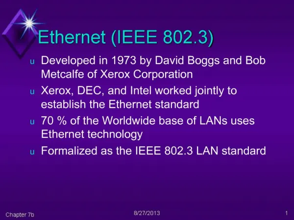
Ethernet Evolution • The Ethernet LAN was developed in the 1970s by Robert Metcalfe and David Boggs. • Since then, it has gone through four generations: Standard Ethernet (10 Mbps), Fast Ethernet (100 Mbps), Gigabit Ethernet (1 Gbps), and 10 Gigabit Ethernet (10 Gbps).
1. Standard Ethernet • The original Ethernet technology with the data rate of 10 Mbps is the Standard Ethernet. • Although most implementations have moved to other technologies in the Ethernet evolution, there are some features of the Standard Ethernet that have not changed during the evolution. • 1.1Characteristics: • Connectionless and Unreliable Service: Ethernet provides a connectionless service, which means each frame sent is independent of the previous or next frame. Ethernet has no connection establishment or connection termination phases. • Ethernet is also unreliable like IP and UDP.
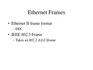
Frame Format: • Frame Length: Ethernet has imposed restrictions on both the minimum and maximum lengths of a frame. • The minimum length restriction is required for the correct operation of CSMA/CD,
1.2 Addressing • Each station on an Ethernet network (such as a PC, workstation, or printer) has its own network interface card (NIC). • The NIC fits inside the station and provides the station with a 6-byte physical address. • The Ethernet address is 6 bytes (48 bits), normally written in hexadecimal notation, with a colon between the bytes. Unicast, Multicast, and Broadcast Addresses: • A source address is always a unicast address-the frame comes from only one station. • The destination address, however, can be unicast, multicast, or broadcast.
If the least significant bit of the first byte in a destination address is 0, the address is unicast; otherwise, it is multicast. • A unicast destination address defines only one recipient; the relationship between the sender and the receiver is one-to-one. • A multicast destination address defines a group of addresses; the relationship between the sender and the receivers is one-to-many. • The broadcast address is a special case of the multicast address; the recipients are all the stations on the LAN. • A broadcast destination address is forty-eight 1s.
Distinguish Between Unicast, Multicast, and Broadcast Transmission • Standard Ethernet uses a coaxial cable (bus topology) or a set of twisted-pair cables with a hub (star topology). • In a unicast transmission, all stations will receive the frame, the intended recipient keeps and handles the frame; the rest discard it. • In a multicast transmission, all stations will receive the frame, the stations that are members of the group keep and handle it; the rest discard it. • In a broadcast transmission, all stations (except the sender) will receive the frame and all stations (except the sender) keep and handle it.
1.3 Access Method • Since the network that uses the standard Ethernet protocol is a broadcast network and requires an access method to control access to the sharing medium. • The standard Ethernet chose CSMA/CD with 1-persistent method.
1.4 Implementation • The Standard Ethernet defined several implementations, but only four of them became popular during the 1980s. • In the nomenclature 10BaseX, the number defines the data rate (10 Mbps), the term Base means baseband (digital) signal, and X approximately defines either the maximum size of the cable in 100 meters (for example 5 for 500 or 2 for 185 meters) or the type of cable, T for unshielded twisted pair cable (UTP) and F for fiber-optic.
1.4.1 10Base5: Thick Ethernet • The first implementation is called 10Base5, thick Ethernet, or Thicknet. • The nickname derives from the size of the cable, which is roughly the size of a garden hose and too stiff to bend with your hands. • 10Base5 was the first Ethernet specification to use a bus topology with an external transceiver (transmitter/receiver) connected via a tap to a thick coaxial cable.
1.4.2 10Base2: Thin Ethernet • The second implementation is called 10Base2, thin Ethernet, or Cheapernet. • 10Base2 also uses a bus topology, but the cable is much thinner and more flexible. • The cable can be bent to pass very close to the stations. • In this case, the transceiver is normally part of the network interface card (NIC), which is installed inside the station.
1.4.3 10Base-T: Twisted-Pair Ethernet • The third implementation is called 10Base-T or twisted-pair Ethernet. • 10Base-T uses a physical star topology. • The stations are connected to a hub via two pairs of twisted cable. • Two pairs of twisted cable create two paths (one for sending and one for receiving) between the station and the hub. Any collision here happens in the hub. • Compared to 10Base5 or 10Base2, the hub actually replaces the coaxial cable as far as a collision is concerned.
1.4.4 10Base-F: Fiber Ethernet • Although there are several types of optical fiber 10-Mbps Ethernet, the most common is called 10Base-F. • 10Base-F uses a star topology to connect stations to a hub. • The stations are connected to the hub using two fiber-optic cables.
Changes in the Standard • The changes that occurred to the 10-Mbps Standard Ethernet. • These changes actually opened the road to the evolution of the Ethernet to become compatible with other high-data-rate LANs. • Bridged Ethernet • The first step in the Ethernet evolution was the division of a LAN by bridges. • Bridges have two effects on an Ethernet LAN: They raise the bandwidth and they separate collision domains. • Switched Ethernet • Instead of having two to four networks, why not have N networks, where N is the number of stations on the LAN? • In other words, if we can have a multiple-port bridge, why not have an N-port switch? • In this way, the bandwidth is shared only between the station and the switch. • In addition, the collision domain is divided into N domains.
Full-Duplex Ethernet • One of the limitations of 10Base5 and 10Base2 is that communication is half-duplex (10Base-T is always full-duplex); a station can either send or receive, but may not do both at the same time. • The next step in the evolution was to move from switched Ethernet to full-duplex switched Ethernet. • The full-duplex mode increases the capacity of each domain from 10 to 20 Mbps. • Note that instead of using one link between the station and the switch, the configuration uses two links: one to transmit and one to receive. • In full-duplex switched Ethernet, there is no need for the CSMA/CD method. • Each link is a point-to-point dedicated path between the station and the switch. • There is no longer a need for carrier sensing; there is no longer a need for collision detection.
MAC Control Layer • Standard Ethernet was designed as a connectionless protocol at the MAC sublayer. • There is no explicit flow control or error control to inform the sender that the frame has arrived at the destination without error. • When the receiver receives the frame, it does not send any positive or negative acknowledgment. • To provide for flow and error control in full-duplex switched Ethernet, a new sublayer, called the MAC control, is added between the LLC sublayer and the MAC sublayer.
2. Fast Ethernet (100 Mbps) – IEEE 802.3u • In the 1990s, some LAN technologies with transmission rates higher than 10 Mbps, such as FDDI and Fiber Channel, appeared on the market. • If the Standard Ethernet wanted to survive, it had to compete with these technologies. • Ethernet made a big jump by increasing the transmission rate to 100 Mbps, and the new generation was called the Fast Ethernet. • The designers of the Fast Ethernet needed to make it compatible with the Standard Ethernet. • The MAC sublayer was left unchanged, which meant the frame format and the maximum and minimum size could also remain unchanged. • By increasing the transmission rate, features of the Standard Ethernet that depend on the transmission rate, access method, and implementation had to be reconsidered.
The goals of Fast Ethernet can be summarized as follows: • Upgrade the data rate to 100 Mbps. • Make it compatible with Standard Ethernet. • Keep the same 48-bit address. • Keep the same frame format.
2.1 MAC Sublayer • A main consideration in the evolution of Ethernet from 10 to 100 Mbps was to keep the MAC sublayer untouched. • However, a decision was made to drop the bus topologies and keep only the star topology. • For the star topology, there are two choices: half duplex and full duplex. • In the half-duplex approach, the stations are connected via a hub; in the full-duplex approach, the connection is made via a switch with buffers at each port . • The access method is the same (CSMA/CD) for the half-duplex approach; for fullduplex Fast Ethernet, there is no need for CSMA/CD. • However, the implementations keep CSMA/CD for backward compatibility with Standard Ethernet.
2.2 Autonegotiation • A new feature added to Fast Ethernet is called autonegotiation. • It allows a station or a hub a range of capabilities. • Autonegotiation allows two devices to negotiate the mode or data rate of operation. • It was designed particularly for the following purposes: • To allow incompatible devices to connect to one another. For example, a device with a maximum capacity of 10 Mbps can communicate with a device with a 100 Mbps capacity (but can work at a lower rate). • To allow one device to have multiple capabilities. • To allow a station to check a hub’s capabilities.
3. Gigabit Ethernet (1 Gbps) – IEEE 802.3z • The need for an even higher data rate resulted in the design of the Gigabit Ethernet Protocol (1000 Mbps). • The IEEE committee calls the Standard 802.3z. • The goals of the Gigabit Ethernet design can be summarized as follows: • Upgrade the data rate to 1 Gbps. • Make it compatible with Standard or Fast Ethernet. • Use the same 48-bit address. • Use the same frame format. • Keep the same minimum and maximum frame lengths. • To support autonegotiation as defined in Fast Ethernet.
4. Ten-Gigabit Ethernet (10 Gbps) – IEEE 802.3ae • The IEEE committee created Ten-Gigabit Ethernet and called it Standard 802.3ae. • The goals of the Ten-Gigabit Ethernet design can be summarized as follows: • Upgrade the data rate to 10 Gbps. • Make it compatible with Standard, Fast, and Gigabit Ethernet. • Use the same 48-bit address. • Use the same frame format. • Keep the same minimum and maximum frame lengths. • Allow the interconnection of existing LANs into a metropolitan area network (MAN) or a wide area network (WAN). • Make Ethernet compatible with technologies such as Frame Relay and ATM. • Ten-Gigabit Ethernet operates only in full duplex mode, which means there is no need for contention; CSMA/CD is not used in Ten-Gigabit Ethernet.