Download
1 / 31
310 likes | 564 Views
Instrumentation Progress. Om Singh Instrumentation Group Leader ASAC Review – October, 14-15, 2010. Outline. NSLS-II Diagnostics Overview Injector Instrumentation Update Storage Ring Instrumentation Update Summary. NSLS-II Diagnostics Systems. *NSLS-II provides BPM Electronics.

E N D
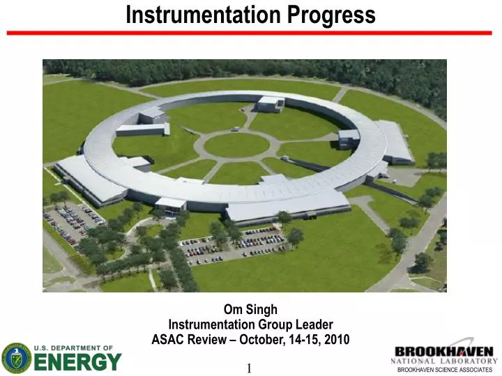
Instrumentation Progress Om Singh Instrumentation Group Leader ASAC Review – October, 14-15, 2010
Outline NSLS-II Diagnostics Overview Injector Instrumentation Update Storage Ring Instrumentation Update Summary
NSLS-II Diagnostics Systems *NSLS-II provides BPM Electronics
Injector Diagnostics Systems Resolution Requirement • Linac rep rate = 10 Hz; • Booster ramp rate = 1 Hz; • Booster revolution frequency = 1.98 MHz; • Storage ring revolution frequency = 378 kHz; • Bunch spacing = ~ 2ns • Bunch length = 15 – 30 ps
Injector Diagnostics Status – LTB Transport Part 1 (Linac Commissioning) 2 Faraday Cups 3 BPM electronics LTB - Part 1 Inside Linac Vault 1 Energy Slit 1 FCT & 1 ICT D. Padrazo B. Kosciuk I. Pinayev K. Vetter J. DellaPenna 6 FLAGS RF Buttons 15 mm Dia. 1 Elliptical Chamber Flange Assembly 2 Circular Chamber Flange Assembly
Layout of Injection Straight Diagnostics Flag 2 BPM 2 BPM (Septum) BPM 1 TL BPM Flag 1 • Two OTR Flags to observe beam position and shape; Flag 1 after septum; and Flag 2 after the first turn • Two BPMs (1&2) to observe circulating and bumped (12 mm) stored beam; One BPM (septum) to observe injected beam (25 mm) • One BPM in the transfer line between DC and pulsed septa for measuring of position of injected beam
Diagnostics Beamlines • Two X-ray synchrotron imaging beamlines with PH camera & CR lenses • 1st BM source point in Cell 22 – to measure emittance • 3PW source point in Cell 22 – to measure energy spread • All optical components are inside tunnel • One Visible synchrotron imaging beamline • 2nd BM source point in Cell 30 – to measure temporal and spatial beam properties • Location (just downstream of injection straight) - ideal to assist injector tuning • A shed for experimental optical table located just outside ratchet wall • Design review held in July, 2010 • Comment – “Proposed design for all beamlines is effective to meet all critical goals for both commissioning and long-term success of the facility” • Status • Final design of beam line components in last stage; followed with procurement for optical components
Mitigation of Resonance Modes in Multipole Chamber – RF Shields Flexible BeCu RF fingers with 50% of opening space Resonance modes With no rf shield • S2 & S4 shifts modes to > 800 MHz 500 MHz S2 S4 S6 • S6 upstream shifts modes to > 800 MHz • S6 downstream does not shift out of band • but can optimize modes location Blednykh; Ferreira Hseuh; Kosciuk
BPM Rack Connections Bulkhead Type N Connectors RG223 Cables The spacing between the type-N bulkhead connectors is 1.50” x 1.75” which is adequate to make the connections manually. B.Kosciuk
RF Cable Junction Box – SR Tunnel Carbon fiber stand • Passive RF Box – Pilot Tone Injection • SiO2 cables – Button to RF Box • LMR-240 – RF Box to Electronics Rack Passive RF Box with Diplexer, couplers, and Isolator Vetter Kosciuk Pursuing use of Stripline coupler in Junction Box in place of Diplexer approach to inject In-Band Cal Tone
Multi Pole SR RF BPM - Optimization • Mechanical thermal and • vibration stability < 0.2 um • Electronic thermal stability • < 0.2 um • Electronics AC stability • < 0.2 um NSLS-II RF BPM (Prototype) AFE DFE RF spring – to mitigate HOM issues 25mm 16mm Multipole Chamber Optimized RF Button
Analysis of Heat Dissipation in the BPM Button ASAC October 09 review Comment - “Concerning the BPM buttons, the committee recommends that calculations of the high frequency RF power deposited in the button geometry should be performed using electromagnetic codes as GDFIDEL, to have an accurate estimate of the heating of the button.” • For 2 mm thick molybdenum button only 14% of beam deposited energy is dissipated in the button1 • The diameter of the button was chosen to place trapped mode frequency off the RF harmonic and power dissipated in the button is a sum of contributions from the individual bunches • For 300 mA beam with 15 psr.m.s. bunch duration the loss factor is 5 mV/pC and power dissipated in the each button will be 31 mW • For 500 mA beam with 30 psr.m.s. bunch duration the loss factor is 0.6 mV/pC and power dissipated in the each button will be 10 mW GDFIDL simulations, A. Blednykh 1I. Pinayev and A. Blednykh, “Evaluation of Heat Dissipation in the BPM Buttons”, PAC’09
RF BPM Electronics - Status • ASAC October 2009 review comment – Presented an in-house BPM development plan • From final report - “The committee recognizes that an alternative to the commercial electronics can be developed but will need time and resources to achieve similar or better performance. It is the opinion of the committee that the project probably has the time to develop a new system if highly skilled and motivated people embark immediately on the project.” • BPM Development Progress – in span of 12 months • Assembled a highly motivated team – July 2009 • Developed BPM system architecture in multi-group collaboration environment to provide high BPM performance & optimized control interface – Oct, 2009 • Started parallel effort to design AFE & DFE hardware and to develop DSP algorithms & control system communication interface – Dec 2009. • Built and tested 7 AFEs and 10 DFEs modules with 100% yield; Built and tested 7 BPM systems and 3 Cell controllers – May, 2010 • Performed beam test at ALS, measuring TBT beam stability of 400 nm – July 2010 • Held a BPM design review with favorable comments – August, 2010
BPM Lab test - TbT Position Results Input Signal (PG = 36 dB) SNR ~ 55 dB J. Mead ~400 nm resolution
ALS Beam Test “2-Cam Fill Pattern” Raw Beam on far end of cable 550MHz LPF followed by 10MHz Bessel 5th-order BPF. This signal is split 4-ways and fed into NSLS-II RF BPM The rms noise on the TBT X and Y position = ~ 400nm
BPM Electronics Design Review Comments • “Develop the interfaces to the control system to support as-yet unspecified high level physics and orbit control applications” • Broke down review comments into categories; in process of generating a working document for AP, Controls, Diagnostics groups. This working document will be integrated into an overall schedule. • “The use of pilot tone to correct for channel-to-channel variation is as yet undemonstrated, but will need to be validated in order to meet long term drift requirement” • In-band pilot tone is planned for injector BPM – simpler filter box design (no diplexer); Brevfreq = 5 times SRrevfreq makes DSP processing easier. • Out of band pilot tone is planned for SR BPM; prototype system to be ready to test in 6-9 months
BPM Electronics Design Review Comments - Continued • “Need to address following issues as soon as possible” • “Eliminate noise observed due to power supply” – • Problem solved - Replaced linear regulator from Linear Technology device to a Micrel device. Also, added filters. • “The glitch problem needs to be understood and remedied as soon as possible “ • Early result indicates that by changing rf amplifier from Hittite to Analog Device mitigates the transient issue. Test data with 2 channels has been collected for 17 hours with no glitch. Further tests are underway. • “The processing gain discrepancy, where the rms variation of signal readings is not reduced as the filter bandwidth is reduced, needs to be understood.” • We are analyzing the problem by having to store and extract 1M turns of data that enables high resolution FFT’s to hunt down perturbations in the sub-hertz regime.
Injector RF BPM Schedule BPM Receivers available at least 3 months prior to System Integration Start
Storage Ring RF BPM Schedule All BPM’s installed and tested including system integration 3 mo prior to start of commissioning After 12-week lag for manufacturing startup, BPM’s are fed in groups of (8) units into NSLS-II System Integration.
SUMMARY • Diagnostics & Instrumentation systems are in final design or in procurement stage • Injector diagnostics installation is on schedule for injection machine commissioning • Diagnostics beamline design in advance stage; procurements to follow • SR RF buttons in production; Injector RF buttons in 1st article acceptance stage • Tunnel work planning in progress for BPM RF junction boxes and cable layout • Resonance modes solution – RF Shield Production units in hand; installation in progress. • RF BPM Electronics • In-house design at advance stage – AFE & DFE spin 2 work in progress • 1st article – injector BPMs 3/1/2011 • 1st article – SR BPMs 8/1/2011 • Production schedule meets system integration and commissioning dates • Installation, system integration and commissioning schedule have been optimized
Acknowledgment B. Bacha, A. Blednykh, A. Borrelli, P. Cameron, W. Cheng, L.B. Dalesio, J. De Long, P. Ilinski, A.J. Della Penna, L. Doom, M. Ferreira, G. Ganetis, W. Guo, H-C Hseuh, Y. Hu, E.D. Johnson, B.N. Kosciuk, S.L. Kramer, S. Krinsky, F. Lincoln, C. Longo, W. Louie, M. Maggipinto, J. Mead, A. Munoz, S. Orban, D. Padrazo, I. Pinayev, J. Ricciardelli, G. Shen, S. Sharma, J. Skaritka, C. Spataro, T. Tanabe, Y. Tian, K. Vetter, W. Wilds, F.J. Willeke, L-H Yu
AFE Development Status (2/2010) Receiver Functional Receiver Diagram • Completed simulation of receiver • Completed laboratory characterization of four ADC’s. Selected Linear Technology LTC2208 • Completed laboratory characterization of BPM receiver (single channel) • Laboratory results confirm compliance with Injector and SR operating requirements based on simulated signal estimates. • Schematic 80% complete • Anticipate board layout complete by end of February • AFE Design meets BPM resolution requirement for both injector and storage ring. • Maximum SNR achieved > 60 dB • At nominal operating conditions, expected resolutions - • Single pass resolution < 5 um • Stored beam resolution < 100 nm • Operational dynamic range of receiver > 100dB BPM Receiver RF Simulation Nominal Operating Conditions (500mA)= -15dBm AT2 Bank AT1 Bank
SR BPMs and Correctors 2 1 BPMs 2 3 1 3 4 6 5 SC SC FC FC SC FC SC • Slow correctors (Qty=6) • Slow response – 2 Hz • Strong strength – 800 μrad • Utilized for – • Alignment • Slow orbit feedback SC SC • Fast correctors (Qty=3) • Fast response – 2 kHz • Weak strength – 15 μrad • Utilized for – • Fast orbit feedback 156 mm slow 100 mm slow 30 mm fast (air core)
SR Diagnostics Hardware Locations (Proposed) 3PW PH/CRL BM - SLM BM PH/CRL Scrapers
ID RF BPM & Stand - Optimization Laser Head Setup #1 with Laser ±35nm ±70nm Vishy ±0.1°C Reflective Target Mounted to Invar Kosciuk, Ravindranath, Bacha, Lincoln