Download
1 / 33
420 likes | 634 Views
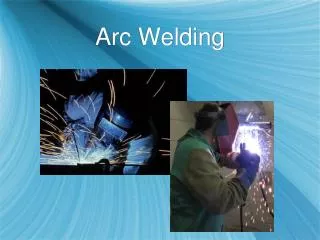
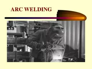
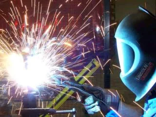
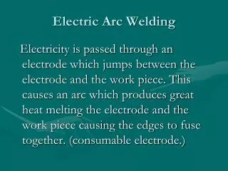
Electric Arc Welding. Electricity is passed through an electrode which jumps between the electrode and the work piece. This causes an arc which produces great heat melting the electrode and the work piece causing the edges to fuse together. (consumable electrode.) . Manual Metal Arc Welding.

E N D
Electric Arc Welding Electricity is passed through an electrode which jumps between the electrode and the work piece. This causes an arc which produces great heat melting the electrode and the work piece causing the edges to fuse together. (consumable electrode.)
Operation of the electrode • The weld pool is protected from oxidation by the gasses produced by melting the chemicals on the electrode coating. • This wire electrode also acts as a filler material to fill the gap between the two parts being joined. • Its third function is to form a slag which protects the weld area form cracking as it allows the joint cool slowly and protect it from oxidation.
Uses This has many operational uses such as repair work to constructional steel. It is ideal for outdoor uses as the gasses needed to form the shield are not blown away.
The Transformer. • This is a device used to change the voltage of A.C. current. It can either step up (increase) or step down (decrease) the voltage. It is necessary to change the voltage when welding thicker or different types of steel.
Transformer-rectifier circuit - A.C. to D.C. • The transformer circuit element of the circuit take AC current and pass it through a step down transformer reducing the voltage, the current is increased. • The low voltage AC is then passed through a series of diodes which only allow current flow in one direction causing it to be changed into Direct Current, this is called a bridge rectifier. • Finally the DC current is passed through a ‘smoothing’ capacitor which causes the current flow more evenly.
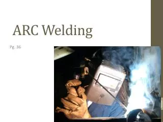
Electric Arc Welding Safety • Pg 370
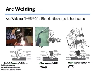
MIG (Metal Inert Gas) welding • Also called MAGS (Metal Arc Gas Shielded) welding • It uses an inert gas such as Argon or CO2 to shield the weld • The bare wire electrode is fed continuously to the weld - semi-automatic process • Can be used on light and heavy plate. • Does not produce a slag and can be used for multi run welds and by robots.
Metal Arc Gas Shielded Welding. (MAGS/MIG) Electricity is passed through an electrode which jumps between the electrode and the work piece. The electrode is touched briefly against the work, this causes an arc which produces great heat melting the electrode and the work piece causing the edges to fuse together.
Metal Arc Gas Shielded Welding. (MAGS/MIG) Uses. • This is one of the most common ways of welding. It can be used to weld sheet metal as well as heavy plates. As the electrode is fed automatically and no slag is formed it is ideal for robotic welding for example car production.
Tungsten Arc Gas Shielded Welding. (TAGS/TIG) Principle. • Two separate current flow in the circuit in this welding process. One is for the arc and is similar to MAGS, the other is a high frequency current used to start the arc. This means an arc is not stuck by touching the work piece as before. Operation. • The arc melts the two edges to be joined as well as the filler rod forming the weld pool. • Gas is pumped through the nozzle protecting the weld pool from oxidation. • The electrode is only to maintain the arc supplying the heat. A consumable filler rod fed by the operator gives the extra metal necessary for the weld pool.
Tungsten Arc Gas Shielded Welding. (TAGS/TIG) Uses. • This is suitable for welding most metals and generally uses DC current for the power source. However when welding aluminium AC is used. This is necessary to breakdown the oxide layer on the outside of the aluminium which has a high melting point. It is also suitable for stainless steel.
Fluxes • Active fluxes – these fluxes are able to dissolve oxide films and will prevent oxides reforming. Zinc chloride is an active flux. Active fluxes are corrosive. Active fluxes remaining on the surface of the steel will corrode the surface in a very short time. • Passive fluxes – all the joint surfaces must be thoroughly cleaned before using a passive flux. It does not have the ability to remove oxides from the surface.
Submerged Arc Welding (SAW) Principle. • Electricity is passed through an electrode which jumps between the electrode and the work piece. The arc produces great heat melting the electrode and the work piece causing the edges to fuse together. The electrode is a wire fed consumable. Operation. • The arc melts the two edges to be joined as well as the electrode forming the weld pool. • The arc is submerged by a granulated flux released from a hopper ahead of it. This flux melts with the heat of the arc protecting the weld pool and forming a slag that controls cooling. Uses. • This is an ideal automated welding process. It is ideal for long runs. It is used for producing steel girders or beams used in construction.
Electro-Slag Welding. Principle. • Electricity is passed between two couples on either side of the plates. This causes the materials in the gap to melt as well as the edges of the plates. This form the weld pool. Operation. • Two pieces of metal are placed between the electrodes. • The electrodes are then closed on the piece causing the circuit to complete. • The resistance in the metal between the electrodes causing them to melt and fuse together. Uses. • This is generally used to join very thick plates together giving a series of overlapping welds until the two plates are fully joined. It is suitable for automatic welding as it is used on large plates usually.
Resistance Welding. (Spot Welding) Principle. • Electricity is passed between two electrodes with the pieces to be joined in between. As the electricity passes through the material the resistance of the metals cause the metals to melt fusing them together. Operation. • Two pieces of metal are placed between the electrodes. • The electrodes are then closed on the piece causing the circuit to complete. • The resistance in the metal between the electrodes causing them to melt and fuse together. Uses. • This is generally used to join light gauge steel sheet metal. Sheets that are too thick will prevent the current from flowing and will not work
Resistance Seam Welding. Principle • This is exactly the same as spot welding except that a continuous is produced. Operation. • The first method is similar to spot welding. Here however the spots are overlapped to form a continuous seam. This is called Stitch welding. • The second method is to replace the electrodes with rollers that cause a continuous seam to be produces. Uses. • This is also used to weld sheet metal except that a continuous seam is required perhaps the production of a water proof tank.
Welding Terms Multi-runs. • This is a method of welding two pieces of thick metal together. A number of welding runs are necessary to build up the gap between the two pieces. Flash back arrestor. • This is a safety device used in gas welding. It prevents the flame from the burning gas traveling through the hose and into the tanks. Dissolved acetylene. • This is the form that acetylene is stored in the tank. The tank is similar to a sponge which absorbs the acetylene. Liquid acetylene would explode in the tank.
Shielded arc. • This is the protection of the weld pool by an inert gas preventing oxidation of the weld. Edge preparation. • This is the preparation of the edges to be welded. They should be free of rust and oil to allow for a quality weld and should be tapered slightly to allow for a good joint. Slag inclusion. • This is a fault where the slag drops into the weld pool and becomes part of it weakening the weld. This is caused by moving the welding apparatus to slowly. Welding at the correct pace will prevent this.
Porosity. • Porosity is the presence of air bubbles in the weld. This is caused by moving the welding apparatus to quickly not giving the weld pool a chance to form properly. This is controlled by welding at the correct pace. Lack of penetration. • This is again a problem with the weld pool. Due to a lack of temperature the edges to be joined do not melt to form the weld pool and fuse together. This can be prevented by setting the welder to the correct power setting.
Gas welding • Metals are fused together and the gap is filled with a filler rod • Oxygen and acetylene are mixed together to generate a flame to melt the weld joint. • Oxygen is pressurised into the cylinder. • Acetylene is dissolved in a porous material called acetone, which will absorb 25 times it’s own volume of Acetylene. Acetylene would explode if it were stored under pressure.