Download
1 / 46
460 likes | 479 Views
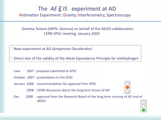
The AE g IS experiment at AD A ntimatter E xperiment : G ravity, I nterferometry, S pectroscopy. Gemma Testera (INFN- Genova) on behalf of the AEGIS collaboration CERN SPSC meeting January 2009. New experiment at AD (Antiproton Decelerator)

E N D
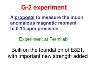
The AE g IS experiment at AD AntimatterExperiment: Gravity, Interferometry, Spectroscopy Gemma Testera (INFN- Genova) on behalf of the AEGIS collaboration CERN SPSC meeting January 2009 • New experiment at AD (Antiproton Decelerator) • Direct test of the validity of the Weak Equivalence Principle for antihydrogen June 2007 : proposal submitted to SPSC October 2007 : presentation to the SPSC January 2008 : recommendation for approval from SPSC 2008 : CERN discussion about the long term future of AD Dec. 2008 : approval from the Research Board of the long term running of AD and of AEGIS
The AE g IS collaboration LAPP, Annecy, France D. Sillou UCBL Lyon, France P.Nedelec Queen’s U Belfast, UK G. Gribakin, H.R.J.Walters CERN M. Doser, A. Dudarev, D. Perini (+ support from T. Eisel, F. Haug, T. Niinikoski) INFN Genova, Italy C. Carraro, V. Lagomarsino, G. Manuzio, G. Testera, S. Zavatarelli MPI-K Heidelberg C. Canali, R. Heyne, A. Fisher,A. Kellerbauer, C. Morhard, U. Warring, C. INFN Firenze, Italy G. Ferrari, M. Prevedelli, G. Tino INFN Milano, Italy I. Boscolo, N. Brambilla,F. Castelli, S. Cialdi, L. Formaro, A. Gervasini, M. Giammarchi, F. Leveraro, A. Vairo Kirchhoff Inst. Of Phys., Heidelberg, Germany M. Oberthaler INR Moscow, Russia A.S. Belov, S. N. Gninenko, V. A. Matveev, A. V. Turbabin ITEP Moscow, Russia W. M. Byakov, S. V. Stepanov, D.S. Zvezhinskij Politecnico Milano, Italy G. Consolati, A. Dupasquier, R. Ferragut, P. Folegati, F. Quasso New York Univ. USA H.H. Stroke Univ. Oslo, Norway O. Rohne, S. Stapnes INFN Pavia-Brescia, Italy G.Bonomi, A. Fontana, A. Rotondi, A. Zenoni IRNE Sofia, Bulgary N. Djurelov Czech Tech. Univ, Prague, Czech Republic V. Petracek, D. Krasnicky, M. Spacek INFN Padova-Trento, Italy R.S. Brusa, D. Fabris, M. Lunardon, S. Mariazzi, S. Moretto, G. Nebbia, S. Pesente, G. Viesti INP Minsk, Belarus G. Drobychev ETH Zurich, Switzerland S.D. Hogan, F. Merkt La. Aime’ Cotton, Orsay, France L. Cabaret, D. Comparat Qatar University I. Y. Al-Qaradawi
The AE g IS physics goals Primary goal: measurement of the Earth gravity acceleration g on antihydrogen • first direct measure of WEP validity for antimatter • direct tests of the EEP only involve matter • high precision limit for WEP violation on matter system • validity for antimatter via (debatable) indirect arguments • no direct measurement on antimatter • WEP violations for antimatter possible in some quantum gravity model Precision : first goal 1% with 105 antihydrogen atoms higher accuracy in the future Additional physics interest : - high precision antihydrogen spectroscopy (CPT tests) - positronium physics (as by product)
Ps Ps Ps Ps The AE g IS experimental method • a) production of a cold beam of antihydrogen (T~100 mK) • • collect 104-105 extremely cold antiprotons (T~0.1K) in a trap • Accumulate a cloud of positrons in a trap: 108 (or more) in some minute • Produce ground state positronium sending the e+ into a nanoporous target : • produce Rydberg positronium via laser excitation • form cold (100 mK) antihydrogen atoms by the charge exchange process • accelerate the antihydrogen atoms to ~ few 100 m/s using electric fields • b)get g through a measurement of the beam deflection with • a Moiré deflectometer AD: 5 MeV pbar Hundreds KeV after a foil Positron beam Catch the low energy fraction of the pbar Cool inside the trap: 10-5 eV (100 mK) Positronium emission
The AE g IS experimental method g Moire’ deflectometer and detector g Cold antiprotons Porous target • The distribution of the vertical coordinates in the detector position shows a spatial modulation • Extract g from this modulated distribution • Use a position sensitive antihydrogen detector e+ • Time to prepare pbar and e+: few hundreds sec • Pulsed Antihydrogen production • 100-1000 antihydrogen/(AEGIS cycle)
The Moiré deflectometer : principle of operation x/a Counts vs vertical coordinate Simulations of the experiment x x L=40 cm L=40 cm a=80 mm Grating period = 80 mm Grating size = 20 cm (2500 slits)
From the AE g IS proposal to a technical design 1 AD antiproton beam 2 3 5 4 6 1 e+ accumulation : 300 K 2 e+ transfer : from 300 K to 4.2K 3 pbar, e+ catching : 4.2 K 4 instrumentation: 5 antihydrogen formation : 100 mK 6 measurement : 4 K -10 K
The overall design is well advanced CERN group
The design of the criostat • SINGLE cryostat housing both the magnets (5T- 1T) and the traps (two cryostats in the proposal) • Interfaces toward room temperature in the instrument middle region (laser access, particle diagnostic) • Dilution refrigerator able to reach < 100 mK in the Hbar formation region (estimated cooling power >500 mW@100mK) • Not standard system: Design&Realization by members of the collaboration (CERN group)
Cooling of trap electrodes in the antihydrogen formation region CERN group • Sandwich composed of Cu-In-Sapphire-In-Cu • Rod electrically insulated using Al2O3 (Alumina) • Development of a suitable Mixing Chamber (3He and 4He) as part of a Dilution Refrigerator to provide cooling at 100 mK of the cold trap region. • Challenges: • Design of cold region to minimize heat loads from thermal radiation and residual gases. • Minimize heat loads from instrumentation and measurement region. • Limited available space • Optimization of heat transfer from electrodes of UCT to the phase boundary (3He /4He) in the mixing chamber with very small temperature gradients (DT<50 mK) • Electrical insulation between the 5 electrodes and other parts and equipment (up to 1kV) Currently 2 different approaches for efficient heat transfer are under investigation:
The AE g IS superconducting magnet CERN group Key points about the magnet design • Long particle storage time requires high field homogeneity: (DB/B :10-4- 10-5) • High antiproton catching efficiency : high field (5T) • Rydberg atoms manipulation difficult in high B: 1 T in the Hbar formation region • B value in the transition region influences the particle transfer efficiency • Several correction coils to tune the field are included • Anti-coils to reduce the field in the measurement region • Design completed • SC wires identified • ready to place the order • Winding process can begin at CERN during summer 2009
The positron accumulator: “Surko type” • 22Na source: > 50 -100 mC • Moderation through solid neon • Accumulation in trap • Buffer gas cooling • 3 108 e+ in few minutes • B= 0.15 -0.2 T
4 stages positron accumulator scheme : under study INR Moscow group Paper in preparation INR-LAPP-UBL Groups • Basic goals • Longer e+ accumulation time • Better efficiency • Improve the vacuum interface with the main system
Positron accumulator Deflectometer & cryostats Racks Laser hut Laser table
Positron injection in the main magnet Prague & INFN Genoa groups e+ accumulator 2m This region has to be free for the g measurement 5T 1T 1T AD antiprotons • 3D Magnetic field calculations with OPERA3D software • Magnetic transport line : 5 T fringe field + additional coils • Particle tracking • Design of the transfer line in advanced status • The delicate point : interference with antiprotons degrading foils Discarded option
e+ e+
The AEGIS trap design : the traps in the high (5T) field INFN Genoa group B= 5 Tesla Antiproton and e+ trap on the same axis (not parallel traps as in the proposal) Antiproton main energy degrader: foil .. has to be movable to allow the e+ injection Pbar and e+ radial compression, preparation to transfer AD-AEGIS vacuum separation foil Pbar catching &e- cooling antiprotons AD e+ from the accumulator
pbar positronium e+ e+ pbar The traps and the particle manipulation in the interaction region (B=1T) : from a single trap to two parallel traps Antiprotons on axis “Standard” transfer from large to “small trap” Ultracooling (electron cooling:tuned circuits +radiation) in the 100 mK region e+ (J. R. Danielson and C. M. Surko Physics of Plasmas13 (2006), 123502) Excitation of diocotron motion of e+ Controlled jump off axis Off axis injection TESTs in progress in Genoa (AEGIS member)
The detector of the antihydrogen formation • We will re-use the ex - ATHENA antihydrogen detector • Readout electronics ready • Tests of the detector already scheduled in the next months (Pavia-Brescia &Padova groups) • The mechanics has to be rebuilt (Padova group) • Works at 70-100 K • Mount it around the ultracold 100 mK trap: a proper thermal shield is under study Replace some CsI crystals with YAP scintillators (fast light output, high yield at low T) detection of the Ps formation : 142 ns decay time • Time to prepare pbar and e+: few hundreds sec • Pulsed Antihydrogen production • Antihydrogen produced within msec: AEGIS will directly measure the antihydrogen velocity by time of flight
Solenoid 4.2 K Detector 80 K Vacuum pipe 4.2 K Mixing chamber zone 0.1 K
Charge exchange cross section (CTMC calculation) INFN Genoa group Cross section cm2 • High cross section • Small effects due to 1 T magnetic field (new result, not included in the proposal: publication in preparation) • Ps velocity of some tens Km/sec : about 100 K
Positronium formation in nanoporous insulators • Implanted positrons with KeV energy scatter off atoms and electrons, slow to eV in few ns • Positronium formation by capture of electrons from collisions • Positronium energy: few eV • Accumulation of positronium in voids • If pores are interconnected orthoPs diffuses out of the film • Positronium loses its energy in collision with the pore walls • Positronium cooling and possible thermalization with the target • AEGIS requirements: • High yield from a cryogenic (100 mK) target • Velocity of Ps corresponding to about 100 K: NOT complete thermalization
Ps cooling in nanoporous materials at low temperature: model AEGIS Trento group Classical model for collisions : ultimate Ps temperature is set by the target temperature Quantum model : Ps in a infinite potential well phonon creation and destruction T(K) • Minimum Ps temperature achievable through collisions: it can be higher than the ground state one. Ground state Ps energy: it depends on the pore size: higher than the target temperature • Ps cooling time: about 10ns < oPs lifetime • Ps emission direction : not isotropic ! this will be of help in AEGIS Pore size (nm) positronium pbar
Realization of ordered nanochannels in silica AEGIS Trento group To obtain nanochannels in silica, silicon has been etched. Pore diameter around 8 nm Pore diameter around 10 nm Pore diameter around 12 nm Pore diameter around 14 nm Si p-type 0.15-0.21 Ohm/cm current 10mA/cm2 15 min Changing these parameters, the pore diameter and density can be changed. Scanning electron microscopy images
Experimental results about the oPs yield: SiO2 target Aegis Tn group Optimization of the target production Yield from cryogenic tyargets S. Mariazzi et al Applied Surf. Science 255 (2008) 191 oPs fraction (%) oPs fraction (%) e+ implantation energy (KeV) e+ implantation energy (KeV) In progress: measurement of the positronium velocity distribution and direction
Experimental results about the yield: Al2O3 target Ordered channels in Al203 Member of AEGIS &coworker LAPP,INP groups Samples annealed at 850 0C: 22 % of the injected positrons forms Positronium escaping in vacuum Samples annealed to 560 0C: no Ps formation
Ageing measurements of the Ps converter AEGIS Poletecnico Milano a) Electron beam facility goals: • Radiation damage measurements on the Ps converter with electrons in the same energy range of the impinging positrons; • Fast measurements due to (high flux of electrons) b) Electron beam facility : • Electron source (Tungsten wire) 10 mA at 2.5 keV • magnetic guide • target support and detectors, • UHV system.
Ps excitation with 2 laser pulses AEGIS Milano&Lab. Aime’ Cotton groups n = 15 – 35 (1709 – 1656nm) Dl = 4nm 5 ns 120 mJ n 205 nm = 0.05 nm 5 ns 20mJ 3 1 R&D Commercial Laser 1700nm 1064 nm OPG 1064 nm 3000nm PPLN 4cm Nd:YAG OPA LN 1cm
LASER OPA Spatial filter OPG
Ps excitation model Member of AEGIS Two pulses: 5 ns 1 3 Doppler broadening T=100 K 93m J/cm2 1mJ/cm2 Motional Stark effect 3 20-30 Energy distance between unperturbed n states Stark broadening Doppler broadening Expected excitation efficiency: 30% Ionization limit
OPG+OPA experimental results Energy out vs Energy in The PPLN crystal allows to cover all the spectrum (fron n=12 up to the ionization) Damage effect of the crystal Required energy Dl~ 4nm Aegis Milano group
Toward ultracold (100 mK) antiprotons Antiprotons in trap cannot be directly cooled to 100 mK Cool antiprotons by collisions with a partner particle stored in the same trap that can be cooled Negative ions: Os- electrons Laser cooling of Os- Ultimate temperature :240 nK Resistive cooling with a resonant tuned circuit + radiation cooling e- antiproton L C • A demonstration of laser cooling of negative ions is needed • Experiment in progress at MPI (members of AEGIS)
The MPI setup for negative Osmium ions trap and laser cooling A. Kellerbauer et al.
Progress toward negative ions laser cooling U. Warring et al, Accepted by Phy. Rev. Lett. (Member of AEGIS) Precise measurement of the transition frequency of Os-: two order of magnitude improvement • Superimpose a Os- beam and a laser beam • Apply an electric field to detach the electrons in the excited ion • Scan the frequency of the laser
AEGIS time schedule • 2009-2010 Begin construction (magnet, cryostat, e+ accumulator, traps ) • Installation in the zone • 2011 and 2012 Run with and without antiprotons (e+ commissioning) • (catch, cool &transfer pbar , e+ accumulation and transfer) • Complete construction and installation • (antihydrogen detector, laser installation) • Rydberg positronium&Hbar formation • Cooling antiprotons to 100 mK • Optimization of the antihydrogen beam • 2014, 2015 …. Run with the grating system and the position sensitive detector • We expect to ask for the first beam time in 2011 • Beam time request : 1/4 of the available AD time for commissioning and physics • Details of the schedule depend on the funding availability (pending requests)
Conclusions • Full CERN approval : dec 2008 • Activity in 2008 • Technical design of the experiment • Continue or begin R&D on critical items • We are ready for construction Already submitted funding requests : Pulsed (quasi CW) Lyman alpha source : Lab. Aime’ Cotton Development of the Antihydrogen Position Sensitive Detector : Oslo group Grating development &Construction : Kirchhoff Inst. Heidelberg Positron&Positronium : INR Moscow AEGIS R&D experiment recognized by INFN Funding discussion with INFN in progress
The Moiré deflectometer : principle of operation x/a Counts vs vertical coordinate • Simulations of the experiment • very high statistics x x L=40 cm L=40 cm a=80 mm Grating period = 80 mm Grating size = 20 cm (2500 slits)
Moire’ deflectometer: simulation Distribution of antihydrogen vertical position x modulo the grating unit a 1500 detected antihydrogen Vz= 300 m/s Ideal detector Time of flight d Grating period x/a Expected position of the minimum count if g=0
F(D,x) 1 D=0 x/a 0 1 1 D=0 x/a 0 1 Data analysis: use of proper digital filter : measured vertical position of every Hbar Total number of particle going thorough a third grating vertically shifted by D D/ a
We do not need a collimated or point like antihydrogen source….. g=0 Ideal detector resolution Antihydrogen position (before filtering) Perfectly collimated source x/a Point like source Transverse energy: 100 mK x/a
…we do not need a point like antihydrogen source … g=0 Extended source Source size (cm) >> grating size Transverse energy: 100 mK x/a • The gravity induced shift does not depend • Antihydrogen radial velocity (it determines the grating and detector size) • Source size • Source vertical position Atom interferometer: it requires high beam collimation
We do not need a monochromatic beam N dN/dT2 Distribution of T2 D/ a ms2 dN/dv Monocromatic source 300 m/s Particles with T2 ( and vz ) distributions shown in the plots m/s
We do need a high resolution position sensitive detector 10 m resolution 17.5 m resolution N 2 p D 2 p D 2 p D3