Download
1 / 19
200 likes | 364 Views
Lecture 9. Demultiplexers Programmable Logic Devices Programmable logic array (PLA) Programmable array logic (PAL). Multiplexer (MUX) Routes one of many inputs to a single output Also called a selector Demultiplexer (DEMUX) Routes a single input to one of many outputs

E N D
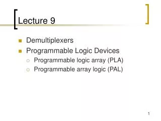
Lecture 9 • Demultiplexers • Programmable Logic Devices • Programmable logic array (PLA) • Programmable array logic (PAL)
Multiplexer (MUX) Routes one of many inputs to a single output Also called a selector Demultiplexer (DEMUX) Routes a single input to one of many outputs Also called a decoder control control Switching networks logic blocks
A0 A1 A2 A3 B0 B1 B2 B3 C0 C1 C2 C3 S1 4:1 MUX 4:1 MUX 4:1 MUX S0 A B C Complex Logic D Computes the output value selected by the control inputs 2:4 DEMUX D0 D1 D2 D3 Logic sharing example
Demultiplexers • Basic concept • Single data input; n control inputs (“selects”); 2n outputs • Single input connects to one of 2n outputs • “Selects” decide which output is connected to the input
01234567 3:8 Demux G S2 S1 S0 A B C Demultiplexers • The input is called an “enable” (G) 1:2 Decoder: Out0 = G S' Out1 = G S 3:8 Decoder: Out0 = G S2' S1' S0' Out1 = G S2' S1' S0 Out2 = G S2' S1 S0' Out3 = G S2' S1 S0 Out4 = G S2 S1' S0' Out5 = G S2 S1' S0 Out6 = G S2 S1 S0' Out7 = G S2 S1 S0 2:4 Decoder: Out0 = G S1' S0' Out1 = G S1' S0 Out2 = G S1 S0' Out3 = G S1 S0
G Out0 Out1 Out0 G S Out2 Out1 Out3 S1 S0 Demultiplexers: Implemtation 2:4 demux 1:2 demux
A n:2n demux can implement any function of n variables Use variables as select inputs Tie enable input to logic 1 Sum the appropriate minterms (extra OR gate) 0 A'B'C'1 A'B'C2 A'BC'3 A'BC4 AB'C'5 AB'C6 ABC'7 ABC 3:8 Demux 1 S2 S1 S0 A B C Demultiplexer as logic block demultiplexer “decodes” appropriate minterms from the control signals
0 A'B'C'D'1 A'B'C'D2 A'B'CD'3 A'B'CD4 A'BC'D'5 A'BC'D6 A'BCD'7 A'BCD8 AB'C'D'9 AB'C'D10 AB'CD'11 AB'CD12 ABC'D'13 ABC'D14 ABCD'15 ABCD0 A'B'C'D'1 A'B'C'D2 A'B'CD'3 A'B'CD4 A'BC'D'5 A'BC'D6 A'BCD'7 A'BCD8 AB'C'D'9 AB'C'D10 AB'CD'11 AB'CD12 ABC'D'13 ABC'D14 ABCD'15 ABCD F1 4:16Demux Enable = 1 F2 F3 A B C D Demultiplexer as logic block F1 = A'BC'D + A'B'CD + ABCD F2 = ABC'D' + ABC F3 = (A'+B'+C'+D')
0 A'B'C'D'E'1234567 012 A'BC'DE'34567 3:8 Demux 3:8 Demux S2 S1 S0 S2 S1 S0 0123 2:4 Demux F S1 S0 01234567 ABCDE 0 AB'C'D'E'1234567 AB'CDE A B 3:8 Demux 3:8 Demux S2 S1 S0 S2 S1 S0 C D C D E E Cascading demultiplexers • 5:32 demux
• • • inputs ANDarray ORarray productterms outputs • • • Programmable logic • Concept: Large array of uncommitted AND/OR gates (actually NAND/NOR gates) • You program the array by making or breaking connections • Programmable block for sum-of-products logic
All two-level functions available • You "program" the wire connections This is a 3-input, 5-term, 4-function programmable logic array (PLA). Connections ("fuse") are designed to break down under high current. After analyzing Boolean equations, software determines which fuses should be blown.
B C A AB B'C AC' B'C' A 1 F0 F1 F2 F3 Example F0 = A + B'C' F1 = AC' + AB F2 = B'C' + AB F3 = B'C + A
A B C D AB A'B' CD' C'D F0 F1 Short-hand notation • Draw multiple wires as a single wire or bus • × signifies a connection Before Programming After Programming F0 = AB + A'B' F1 = CD' + C'D
A B C A'B'C' A'B'C A'BC' A'BC AB'C' AB'C ABC' ABC A B C F1 F2 F3 F4 F5 0 0 0 0 0 1 1 0 0 0 1 0 1 0 1 1 0 1 0 0 1 0 1 1 0 1 1 0 1 0 1 0 1 0 0 0 1 0 1 1 1 0 1 0 1 0 1 0 1 1 0 0 1 0 1 0 1 1 1 1 1 0 0 1 F1 F2 F3 F4 F5 PLA example Think of as a memory-address decoder F1 = ABC F2 = A + B + C F3 = A' B' C' F4 = A' + B' + C' F5 = A xor B xor C 0 1 0 Memory bits 0 1 0 1 1
We've been looking at PLAs Fully programmable AND/OR arrays Programmable array logic (PAL) Programmable AND array OR array is prewired Cheaper and faster than PLAs PLAs versus PALs
A B C D W X Y Z0 0 0 0 0 0 0 00 0 0 1 0 0 0 10 0 1 0 0 0 1 10 0 1 1 0 0 1 00 1 0 0 0 1 1 00 1 0 1 1 1 1 00 1 1 0 1 0 1 00 1 1 1 1 0 1 11 0 0 0 1 0 0 11 0 0 1 1 0 0 01 0 1 0 X X X X1 0 1 1 X X X XA B C D W X Y Z0 0 0 0 0 0 0 00 0 0 1 0 0 0 10 0 1 0 0 0 1 10 0 1 1 0 0 1 00 1 0 0 0 1 1 00 1 0 1 1 1 1 00 1 1 0 1 0 1 00 1 1 1 1 0 1 11 0 0 0 1 0 0 11 0 0 1 1 0 0 01 0 1 0 X X X X1 0 1 1 X X X X 1 1 0 0 X X X X 1 1 0 1 X X X X 1 1 1 0 X X X X 1 1 1 1 X X X X Example: BCD to Gray code A A AB AB 00 01 11 10 00 01 11 10 CD CD 00 0 0 X 101 0 1 X 111 0 1 X X10 0 1 X X 00 0 1 X 001 0 1 X 011 0 0 X X10 0 0 X X D D C C B B K-map for W K-map for X A A AB AB 00 01 11 10 00 01 11 10 CD CD 00 0 1 X 001 0 1 X 011 1 1 X X10 1 1 X X 00 0 0 X 101 1 0 X 011 0 1 X X10 1 0 X X D D C C B B K-map for Y K-map for Z
A B C D W X Y Z Wiring a PLA Minimized functions: W = A + BC + BD X = BC' Y = B + C Z = A'B'C'D + BCD + AD' + B'CD'
Wiring a PAL Minimized functions: W = A + BC + BD X = BC' Y = B + C Z = A'B'C'D + BCD + AD' + B'CD' Fine example for the use of PAL (because no shared AND terms) Many AND gates wasted, but still faster and cheaper than PLA
PLA: No shared logic terms in this example 10 decoded functions (10 AND gates) PAL: Z requires 4 product terms Need a PAL that handles 4 product terms for each output 16 decoded functions (16 AND gates) 6 unused AND gates Implementation comparison • Example is a good candidate for PALs: • 10 of 16 possible inputs are decoded • No sharing among AND terms