Download

1 / 9
160 likes | 387 Views
Contact Mechanics in Hip Prosthesis. Dan Flavin. Background. Prosthetic hips a common replacement joint in the US. Artificial ball and socket to replace worn biological parts. Hip joint formed of two parts: Femoral implant with head ( monobloc or modular)

E N D
Contact Mechanics in Hip Prosthesis Dan Flavin
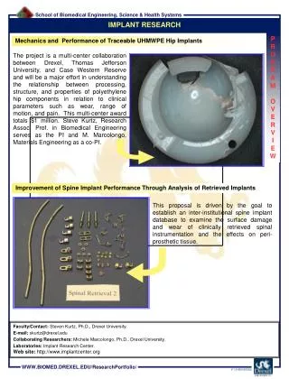
Background • Prosthetic hips a common replacement joint in the US. • Artificial ball and socket to replace worn biological parts. • Hip joint formed of two parts: • Femoral implant with head (monobloc or modular) • Acetabular cup (monobloc or modular) • Lubricated with synovial fluid (non-Newtonian)
Types • Three major categories: • Metal on Polymer (MOP) • Standard 1970s , common to present • Metal femur head, UHMWPE acetabular cup • Metal on Metal (MOM) • Both head and cup metal (316L or CoCr) • Common 1990s-2010 (recall) • Ceramic on Ceramic (COC) • Modular metal femur with ceramic head, ceramic liner on cup • Common 1990s to present • Other combinations (COP, MOC) also available • All available in varying head sizes, clearances • Larger head less likely to dislocate, but has higher friction and inertia • MOP and MOM tend to shed debris, COC can fracture • All have similar lifespans
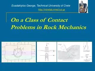
The Problem • To address wear and debris problems, need to determine contact area and loading. • This data can then be combined with lab experiments to build full understanding of action at joint. • Complicated by convexity – methods include “flattening” into Hertzian problem. • Apply FEA with COMSOL to determine contact area, to allow further analsis.
Conclusion • Segmentation of graph suggests finer mesh required near contact point • Complete FUBAR of MOP results suggests failure in model for larger displacements. • Use load stepping or larger displacement plugin to allow better control of model