Download
1 / 1
10 likes | 186 Views
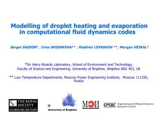
EFFECTS OF DROPLET BREAKUP, HEATING AND EVAPORATION ON AUTOIGNITION OF DIESEL SPRAYS. S. Martynov 1 , S. Sazhin 2 , C. Crua 2 , M. Gorokhovski 3 , A. Chtab 4 , E. Sazhina 2 , K. Karimi 2 , T. Kristyadi 2 , M. Heikal 2

E N D
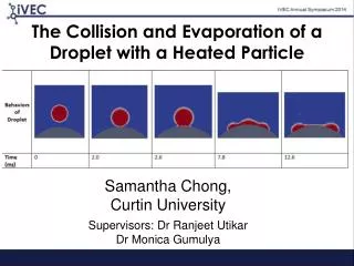
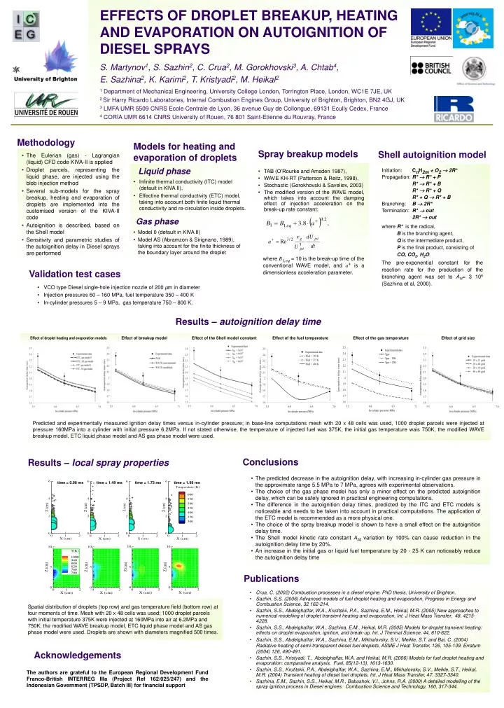
EFFECTS OF DROPLET BREAKUP, HEATING AND EVAPORATION ON AUTOIGNITION OF DIESEL SPRAYS S. Martynov1, S. Sazhin2, C. Crua2, M. Gorokhovski3, A. Chtab4, E. Sazhina2, K. Karimi2, T. Kristyadi2, M. Heikal2 1Departmentof Mechanical Engineering, University College London, Torrington Place, London, WC1E 7JE, UK 2 Sir Harry Ricardo Laboratories, Internal Combustion Engines Group, University of Brighton, Brighton, BN2 4GJ, UK 3LMFA UMR 5509 CNRS Ecole Centrale de Lyon, 36 avenue Guy de Collongue, 69131 Ecully Cedex, France 4CORIA UMR 6614 CNRS University of Rouen, 76 801 Saint-Etienne du Rouvray, France Methodology Models for heating and evaporation of droplets Shell autoignition model Spray breakup models • The Eulerian (gas) - Lagrangian (liquid) CFD code KIVA-II is applied • Droplet parcels, representing the liquid phase, are injected using the blob injection method • Several sub-models for the spray breakup, heating and evaporation of droplets are implemented into the customised version of the KIVA-II code • Autoignition is described, based on the Shell model • Sensitivity and parametric studies of the autoignition delay in Diesel sprays are performed Liquid phase Initiation: CnH2m + O2 2R* Propagation: R* R* + P R* R* + B R* R* + Q R* + Q R* + B Branching: B 2R* Termination: R* out 2R* out where R* is the radical, B is the branching agent, Q is the intermediate product, P is the final product, consisting of CO, CO2, H2O. The pre-exponential constant for the reaction rate for the production of the branching agent was set to Af4= 3 106 (Sazhina et al, 2000). • TAB (O’Rourke and Amsden 1987), • WAVE KH-RT (Patterson & Reitz, 1998), • Stochastic (Gorokhovski & Saveliev, 2003) • The modified version of the WAVE model, which takes into account the damping effect of injection acceleration on the break-up rate constant: • Infinite thermal conductivity (ITC) model (default in KIVA II), • Effective thermal conductivity (ETC) model, taking into account both finite liquid thermal conductivity and re-circulation inside droplets. Gas phase • Model 0 (default in KIVA II) • Model AS (Abramzon & Sirignano, 1989), taking into account for the finite thickness of the boundary layer around the droplet where B1,eq = 10 is the break-up time of the conventional WAVE model, and a+ is a dimensionless acceleration parameter. Validation test cases • VCO type Diesel single-hole injection nozzle of 200 µm in diameter • Injection pressures 60 – 160 MPa, fuel temperature 350 – 400 K • In-cylinder pressures 5 – 9 MPa, gas temperature 750 – 800 K. Results – autoignition delay time Effect of droplet heating and evaporation models Effect of breakup model Effect of the Shell model constant Effect of the fuel temperature Effect of the gas temperature Effect of grid size Predicted and experimentally measured ignition delay times versus in-cylinder pressure; in base-line computations mesh with 20 x 48 cells was used, 1000 droplet parcels were injected at pressure 160MPa into a cylinder with initial pressure 6.2MPa. If not stated otherwise, the temperature of injected fuel was 375K, the initial gas temperature wais 750K, the modified WAVE breakup model, ETC liquid phase model and AS gas phase model were used. Conclusions Results – local spray properties • The predicted decrease in the autoignition delay, with increasing in-cylinder gas pressure in the approximate range 5.5 MPa to 7 MPa, agrees with experimental observations. • The choice of the gas phase model has only a minor effect on the predicted autoignition delay, which can be safely ignored in practical engineering computations. • The difference in the autoignition delay times, predicted by the ITC and ETC models is noticeable and needs to be taken into account in practical computations. The application of the ETC model is recommended as a more physical one. • The choice of the spray breakup model is shown to have a small effect on the autoignition delay time. • The Shell model kinetic rate constant Af4 variation by 100% can cause reduction in the autoignition delay time by 20%. • An increase in the initial gas or liquid fuel temperature by 20 - 25 K can noticeably reduce the autoignition delay time time = 0.98 ms time = 1.49 ms time = 1.73 ms time = 1.98 ms Publications • Crua, C. (2002) Combustion processes in a diesel engine. PhD thesis, University of Brighton. • Sazhin, S.S. (2006) Advanced models of fuel droplet heating and evaporation, Progress in Energy and Combustion Science, 32 162-214. • Sazhin, S.S., Abdelghaffar, W.A., Krutitskii, P.A., Sazhina, E.M., Heikal, M.R. (2005) New approaches to numerical modelling of droplet transient heating and evaporation, Int. J Heat Mass Transfer, 48. 4215-4228. • Sazhin, S.S., Abdelghaffar, W.A., Sazhina, E.M., Heikal, M.R. (2005) Models for droplet transient heating: effects on droplet evaporation, ignition, and break-up, Int. J Thermal Science, 44, 610-622. • Sazhin, S.S., Abdelghaffar, W.A., Sazhina, E.M., Mikhalovsky, S.V., Meikle, S.T. and Bai, C. (2004) Radiative heating of semi-transparent diesel fuel droplets, ASME J Heat Transfer, 126, 105-109. Erratum (2004) 126, 490-491. • Sazhin, S.S., Kristyadi, T., Abdelghaffar, W.A. and Heikal, M.R. (2006) Models for fuel droplet heating and evaporation: comparative analysis, Fuel, 85(12-13), 1613-1630. • Sazhin, S.S., Krutitskii, P.A., Abdelghaffar, W.A., Sazhina, E.M., Mikhalovsky, S.V., Meikle, S.T., Heikal, M.R. (2004) Transient heating of diesel fuel droplets, Int. J Heat Mass Transfer, 47. 3327-3340. • Sazhina, E.M., Sazhin, S.S., Heikal, M.R., Babushok, V.I., Johns, R.A. (2000) A detailed modelling of the spray ignition process in Diesel engines. Combustion Science and Technology, 160, 317-344. Spatial distribution of droplets (top row) and gas temperature field (bottom row) at four moments of time. Mesh with 20 x 48 cells was used; 1000 droplet parcels with initial temperature 375K were injected at 160MPa into air at 6.2MPa and 750K; the modified WAVE breakup model, ETC liquid phase model and AS gas phase model were used. Droplets are shown with diameters magnified 500 times. Acknowledgements The authors are grateful to the European Regional Development Fund Franco-British INTERREG IIIa (Project Ref 162/025/247) and the Indonesian Government (TPSDP, Batch III) for financial support