Download
1 / 61
610 likes | 632 Views
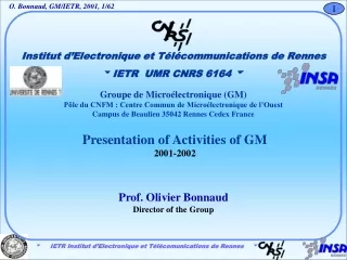
Institut d’Electronique et Télécommunications de Rennes IETR UMR CNRS 6164 . Groupe de Microélectronique (GM) Pôle du CNFM : Centre Commun de Microélectronique de l’Ouest Campus de Beaulieu 35042 Rennes Cedex France. Presentation of Activities of GM 2001-2002. Prof. Olivier Bonnaud

E N D
Institut d’Electronique et Télécommunications de Rennes • IETR UMR CNRS 6164 Groupe de Microélectronique (GM) Pôle du CNFM : Centre Commun de Microélectronique de l’Ouest Campus de Beaulieu 35042 Rennes Cedex France Presentation of Activities of GM 2001-2002 Prof. Olivier Bonnaud Director of the Group
98 GM 1989 MARGAUX GM/Rennes/France/Europe Champagne Paris Rennes Camembert
Main equipment - LPCVD, APCVD, SAPCVD, sputtering, RIE, Evaporator - C(V,T) I(V,T), Hall - Workstations Cleanroom of CCMO - photolithography - furnaces, evaporation - SEM, ellipsometer - talystep Recent equipment - semiconductor parameter analyser HP4155 - POCl3 doping process - in-situ doped silicon SAPCVD arsenic line Cider Introduction 2 GM equipment SAINT-MALO Brittany RENNES GM
CCMO Centre Commun de Microélectronique de l’Ouest Pôle de Rennes du CNFM Comité National de la Formation en Microélectronique - one of the twelve French microelectronics centers devoted to Education - Silicon technology facilities - the cost of the facilities imposes to share the functionning expenses with research activities - GM is the common research laboratory with CCMO
All these facilities are available for basic education and research activities and more especially for international cooperation.
OP2 DISPOSITIFS : TECHNOLOGIE, CARACTERISATION, MODÉLISATION Operations de l’équipe GM de l’IETR Resp. Olivier BONNAUD (D.E) OP1 ELABORATION DE COUCHES MINCES - SILICIUM POLYCRISTALLIN, ISOLANTS - APPLICATION AUX MICROTECHNOLOGIES Michel SARRET (D.E.) Dépôts CVD par différentes techniques basse température de couches polycristallines Si et alliage Si /Ge non dopées ou dopées in-situ (P, As, B) Mise au point d’étapes de la microtechnologie de surface Etapes technologiques de fabrication de composants Couches minces et épaisses de Si-poly, silice, nitrure, ITO et métaux pour application aux microtechnologies de surface Tayeb MOHAMMED-BRAHIM (D.E) Réalisation technologique de transistors et circuits en couches minces en Si-poly Réalisation et caractérisation de capteurs intégrés en microtechnologie de surface : antennes planaires pour circuits micro-onde, capteurs biologiques, capteurs magnétiques, capteurs d’humidité,…. Caractérisation, modélisation, simulation de couches et dispositifs Caractérisation, analyse et fiabilité des technologies VLSI, smart power
Activities of GM APPLIED STUDIES photovoltaïc diodes films antennas microtech nology TFT AMLCD Flat pannel displays techno. STM Tours Si-poly techno. STM Rousset smartsensor TFT VLSI techno. STM Rennes technology elaboration characterization modelling FONDAMENTAL STUDIES
Thematics • Large area electronics • - Solid phase crystallization • - Laser crystallization • CMOS TFTs technology • Microelectronics • Reliability • Microsystems • - basic elements • - applications • - stress measurements • Conclusion
OUTLINE • Large area electronics • - Solid phase crystallization • - Laser crystallization • CMOS TFTs technology • Microelectronics • Reliability • Microsystems • - basic elements • - applications • - stress measurements • Conclusion
Large area electronics (1) Large area electronics for several applications: - flat panel displays - surface micro-machining - sensors and actuators - 3-D microelectronics Electronics based on polysilicon thin film transistors (TFT) Large area substrate: glass substrate and future polymers Thin film transistor technology, silicon based, low temperature compatible - solid phase crystallization (SPC) - pulsed Excimer laser crystallization - pulsed YAG laser crystallization
amorphous polycrystalline Large area electronics (3) Material problems: the usual amorphous silicon electronics presents limitations Amorphous silicon mobility is much lower then polycrystalline silicon one. The polysilicon electronics is compatible with the electronic command specially for the drivers and converters directly processed on the flat panel display. After O. Bonnaud, POLYSE’98
- silicon deposition process modification, -e + Large area electronics (4) Objectives: - high field effect mobility - low temperature compatible process - high reproducibility - low cost Three approaches were used to improve the TFT's electrical behaviour: - crystallization modification, - hydrogen passivation
S S G G D D Thin Thin Film Transistor Film Transistor Al 300 Al 300 nm nm APCVD SiO APCVD SiO 100 100 nm nm 2 2 N N LPCVD LPCVD Poly Poly -Si 150 -Si 150 nm nm + + Undoped Undoped LPCVD LPCVD Poly Poly -Si 150 -Si 150 nm nm APCVD SiO APCVD SiO 250 250 nm nm 2 2 Glass substrate Glass substrate Large area electronics (5) Process developed at GMV: planar structure involving in-situ doped polysilicon thin films
Cross-sectional view of the polysilicon layers N-doped polysilicon Undoped polysilicon Oxide 100nm 100nm substrate Double-layer structure Mono-layer structure Large area electronics (6) Solid phase crystallization: - modification of the process, - in-situ doping involvement
-3 -3 4.0x10 4.0x10 -3 -3 3.0x10 3.0x10 -3 -3 2.0x10 2.0x10 -3 -3 1.0x10 1.0x10 V = 20 V GS 0.0 0.0 V = 16 V GS ( A ) ( A ) DS DS I I V = 20 V GS V = 16 V GS 0 5 10 15 20 0 5 10 15 20 V V ( V ) ( V ) DS DS Large area electronics (7) Output characteristics mono-layer Poly-Si TFT double-layer poly-Si TFT Mobility: 110 cm2/Vs Mobility: 63cm2/Vs For the same gate voltage, IDS is higher for the mono-layer structure. (GMV, MRS’97, San Francisco-CA)
Large area electronics (8) Solid phase crystallization The so-called mono-layer process gives much better features. This work shows the importance of the process on the final electrical behavior . Because this crystallization technique is very long (12 hours for 50 substrates), other techniques were developed. (GMV, MRS’97, San Francisco-CA)
160 1E-4 1 shot 1E-5 140 2 shots 2 550 mJ /cm 10 shots 1E-6 120 1E-7 100 1E-8 80 1E-9 60 1E-10 1E-11 40 1E-12 20 700 650 600 450 500 550 Drain-source current (A) Field effect mobility cm2/V.s : 1 shot : 2 shots : 5 shots : 10 shots -10 0 10 20 -20 Gate source voltage (V) 2 Laser fluence (mJ/cm2) Large area electronics (9) Pulsed Excimer laser crystallization: large area beam ( 20 cm2) Optimization of the crystallization process Process duration : few seconds by wafer (After GMV/SOPRA SA , MRS’98 Boston-MA)
Large area electronics (10) Pulsed Excimer laser crystallization Improvement of the mobility during the last seven years (After GMV/SOPRA , IS&T/SPIE2001, San José-CA)
Large area electronics (11) Pulsed Nd:YVO4 laser crystallization Scanning of a narrow beam : very large grains and very high mobility (350 cm2/Vs – world record in 1999) not far from SOI technology features Crystallization duration : 30min by wafer (After GMV/IPE Stuttgart , IEDM 1999, Washington-DC)
-3 10 µ=356 cm²/V.s -4 10 S=0.36 V/dec V = 0.8V -5 10 T 1.5 µm -6 10 µ=217 cm²/V.s (A) -7 10 S=0.32 V/dec = 1V V DS DS V = 0.77V -8 T 10 I -9 10 -10 10 -11 10 20 -20 -10 0 10 V (V) GS Large area electronics (12) Pulsed Nd:YVO4 laser crystallization Reproducibility of n type and p type process Improvement of electron mobility at a maximum of 450 cm2/Vs After E-MRS2000 Partners : IPE Stuttgart, SOPRA SA, Iena Univ.
P N ( e) S G D S G D P N APCVD gate silicon oxide ( f) + P poly Si aluminum electrodes glass substrate ( g) ( d) Large area electronics (12) CMOS TFTs process using in-situ doped polysilicon films undoped poly Si ( a) isolation: SiO 2 N P ( b) + N poly Si ( c)
Large area electronics (13) CMOS TFTs process Fabrication on the same substrate NMOS and PMOS TFTs: first results (After GMV/LSI , submitted to ICMP’2001, Pirenopolis) Collaboration France/Brazil and Europe (ALFA programme)
Large area electronics (14) CMOS TFTs process inverter (After GMV/LSI , ICMP’2001, Pirenopolis) Potential applications to smart sensors, AMLCD
30 (W/L)N =(W/L)P = 20µm/60µm 140 25 V = 25V 120 DD 100 20 I OUT (nA) 80 15 VOUT (V) IOUT 60 10 VOUT 40 5 20 0 0 6 8 10 12 VIN (V) Large area electronics (15) CMOS TFTs process inverter (After GMV/LSI , accepted to SID IDCS’2002, Seoul, (Korea)
OUTLINE • Large area electronics • - Solid phase crystallization • - Laser crystallization • CMOS TFTs technology • Microelectronics • Reliability • Microsystems • - basic elements • - applications • - stress measurements • Conclusion
Microelectronics Reliability (1) Reliability: a need An IC’s process contains more or less 500 elementary steps (8 weeks) The steps govern : - the initial functioning of the circuit (specifications), - the behavior all along the life under stress (electrical, mechanical, thermal, chemical, radiative, etc….) Two objectives: - fabricate the IC’s with their functional specifications, - predict its evolution in function of their mission profile. Solutions: - find the several failure origins - analyze these failures: definitive or curable, - analyze the failure mechanisms and their effects on the device, - find rapid indicators if possible during the process or just at the end.
Microelectronics Reliability (2) Reliability: gate oxide lifetime Example of one unique measure indicator : a current measurement is enough to predict the time to fail. The importance of this approach is increasing. Experiments were performed in the company. After STMicroelectronics/GMV, X. Gagnard & O. Bonnaud, SPIE 2000
Microelectronics Reliability (3) Application of the fast indicator to leakage interpoly oxide Failed capacitor Good capacitor * Local diminution of gate oxide (bird peak), affects indicator which is more important for failed capacitor * Not detected by Ebd and Qbd on the same capacitor After STMicroelectronics/GMV, X. Gagnard & O. Bonnaud, IPFA 2001
Microelectronics (4) Reliability: tunnel gate oxide lifetime Cooperation with STMicroelectronics Rousset. Improvement of EEPROM reliability (number of cycles). Experiments performed in the company, too. After STMicroelectronics/GMV, K. Ogier & O. Bonnaud, SPIE 1998
Microelectronics (5) Wafer Level Accelerated test for ionic contamination control on VDMOS transistors in Bipolar/CMOS/DMOS
OUTLINE • Large area electronics • - Solid phase crystallization • - Laser crystallization • CMOS TFTs technology • Microelectronics • Reliability • Microsystems • - basic elements • - applications • - stress measurements • Conclusion
3 2 1 MEMs: basic element (1) Deep trenches filled by polysilicon: numerous microelectronics applications After GMV/ST collaboration 1998- 2001
MEMs: basic element (2) Polysilicon based cantilever on silicon substrate After Microwave & Opt. Techn. Let., 2000, MME97 After GMV results 2001
MEMs: basic elements (4) Polysilicon based cantilever on silicon substrate
MEMs: basic elements (5) Polysilicon based cantilever on silicon substrate cantilever on the substrate cantilever released After GMV results 2001
MEMs: basic elements (6) Polysilicon based bridge on silicon substrate After GMV results 2001
MEMs: basic elements (6) *Bridges (GMV 2001) Width from 5 to 30 µm Length from 10 to 250 µm) With or without holes (1 or 2 lines) After GMV results 2001
Silicon platform Polysilicon MEMs: basic elements (7) Physical realization: bridge used as micro-filament heating element in micro-sensors After E. Simoes,et al., Proceedings MME'97 GMV/LSI cooperation
F F F elec elec elec 1 1 1 2 2 Þ 1 control electrodes Þ 2 contact electrodes Substrate Substrate BRIDGE CANTILEVER MEMs: basic elements (8) Polysilicon based microswitches: - cantilever electrostatically moved - bridge with central contact After GMV report 1998
MEMs: basic element (9) Polysilicon based microtips: 10µm thick SAPCVD deposited After CAPES/COFECUB report 1999 LSI (Brazil) - GMV cooperation
Reference electrode Auxiliar electrode Detection electrodes 270 µm 80 µm 20 µm 30 µm 5 µm 90 µm 340 µm MEMs application : medical tips (1) After LSI, 1999 (GMV cooperation)
MEMs application : medical tips (2) After Process 2001 GMV/LSI