Download
1 / 56
590 likes | 800 Views
Fundamentals of Electrochemistry CHEM*7234 CHEM 720. Section 5: Voltammetric Methods. Voltammetric Methods. Historical Electrolysis at DME -1920’s Usually 3-electrode cells. Measurement of current that results from the application of potential.

E N D
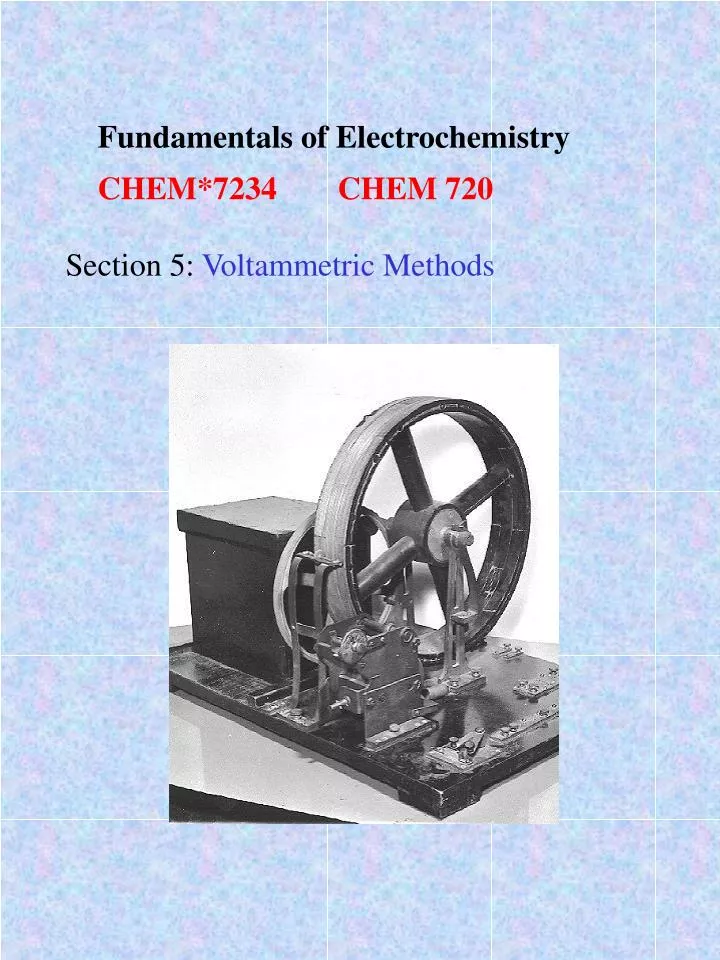
Fundamentals of Electrochemistry • CHEM*7234 CHEM 720 Section 5: Voltammetric Methods
Voltammetric Methods • Historical • Electrolysis at DME -1920’s • Usually 3-electrode cells • Measurement of current that results from the application of potential. • Different voltammetric techniques are distinguished primarily by the potential function that is applied to the working electrode and by the material used as the working electrode.
Types of Voltammetry Polarography Linear sweep and Cyclic Voltammetry Hydrodynamic Voltammetry Pulsed methods AC Voltammetry (not here) ip= 2.69 x 10⁵ n3/2 A DO1/2v1/2 CO It is instructive to start with Polarography Voltammetry at a dropping mercury electrode
Polarography uses mercury droplet electrode that is regularly renewed during analysis. • Applications: • Metal ions (especially heavy metal pollutants) - high sensitivity. • Organic species able to be oxidized or reduced at electrodes: quinones, reducing sugars and derivatives, thiol and disulphide compounds, oxidation cofactors (coenzymes etc), vitamins, pharmaceuticals. • Alternative when spectroscopic methods fail.
History Jaroslav Heyrovský was the inventor of the polarographic method, and the father of electroanalytical chemistry, for which he was the recipient of the Nobel Prize. His contribution to electroanalytical chemistry can not be overestimated. All modern voltammetric methods used now in electroanalytical chemistry originate from polarography. On February 10, 1922, the "polarograph" was born as Heyrovský recorded the current-voltage curve for a solution of 1 M NaOH. Heyrovský correctly interpreted the current increase between -1.9 and -2.0 V as being due to deposition of Na+ ions, forming an amalgam.
Typical polarographic curves (dependence of current I on the voltage E applied to the electrodes; the small oscillations indicate the slow dropping of mercury): lower curve - the supporting solution of ammonium chloride and hydroxide containing small amounts of cadmium, zinc and manganese, upper curve - the same after addition of small amount of thallium. Swedish king Gustav Adolf VI awards the Nobel Prize to Heyrovskýin Stockholm on 10.12.1959
Potential Ramps Linear sweep Polarography In order to derive the the current response one must account for the variation of drop area with time: A = 4(3mt/4d)2/3 = 0.85(mt)2/3 Density of drop Mass flow rate of drop We can substitute this into Cottrell Equation (see Mass Transport Notes) i(t) = nFACD1/2/ 1/2t1/2
We also replace D by 7/3D to account for the compression of the diffusion layer by the expanding drop Giving the Ilkovich Equation: id = 708nD1/2m2/3t1/6C I has units of Amps when D is in cm2s-1,m is in g/s and t is in seconds. C is in mol/cm3 This expression gives the current at the end of the drop life. The average current is obtained by integrating the current over this time period iav = 607nD1/2m2/3t1/6C
The diffusion current is determined by subtracting away the residual current Further improvements can be made by reducing charging currents (see Pulse methods later) E1/2 = E0 + RT/nF log (DR/Do)1/2 (reversible couple) Usually D’s are similar so half wave potential is similar to formal potential. Also potential is independent of concentration and can therefore be used as a diagnostic of identity of analytes. For example
Organic reductions often involve hydrogen ions • R + nH+ + ne RHn • Good buffering reqd in organic polarography Metal Complexes • MLp + ne + Hg M(Hg) + pL • Difference between half-wave potential for complexed and uncomplexed metal ion is given by: • E1/2(c) - E1/2(free) = • RT/nF ln Kd - RT/nF p ln [L] +RT/nF ln (D free/D (c))1/2 • Stoichiometry can thus be determined by plotting • E1/2 versus [L] • Also possible to improve resolution between neighbouring waves by carefully choosing ligand and concentration
Heyrovsky-Ilkovich Equation • Describes wave shape for reversible systems (with fast electron transfer kinetics) • E = E1/2 + RT/nF ln((id - i)/i) • Plot E vs log((id - i)/i) gives straight line of slope 0.059/n • Convenient way to get n • Intercept is half wave potential • Irreversible systems • The waves are more “drawn out” than for reversible systems • Limiting currents still show a linear function of concentration • Shape of polarogram is given by: • E = E0 + RT/nF ln (1.35kf((id - i)/i)(t/D)1/2) • transfer coefficient forward rate constant
Charging Currents : first look • Drop acts as capacitor • Double layer • Since potential change during drop life is very small we can neglect charging changing with potential • charging thus depends on time and electrode area ic = dq/dt = (E-Epzc)Cdl dA/dt but A = 4(3mt/4d)2/3 = 0.85(mt)2/3 ic = 0.00567 (E-Epzc) Cdl m2/3t-1/3 so I(total) = id + ic = kt1/6 + k’t-1/3
Charging current sets limit of detection Various ways of reducing it e.g., Sample current at end of drop life (TAST polarography) Other methods involve Pulse voltammetry -see later
Voltammetry • The supporting electrolyte • Ensures diffusion control of limiting currents by eliminating migration currents • Table: Limiting currents observed for 9.5 x 10⁻⁴ M PbCl2 as a function of the concentration of KNO3 supporting electrolyte • At low inert electrolyte concentration, a large fraction of the total current is due to migration current - currents due to electrostatic attraction of ion for electrode • For sol’n 1, Imigration = 17.6 - 8.45 = 9.2 A; Idiffusion = 8.45 mA
Cyclic Voltammetry • potential is continuously changed as a linear function of time. The rate of change of potential with time is referred to as the scan rate (v). • cyclic voltammetry, in which the direction of the potential is reversed at the end of the first scan. Thus, the waveform is usually of the form of an isosceles triangle. • advantage that the product of the electron transfer reaction that occurred in the forward scan can be probed again in the reverse scan. • powerful tool for the determination of formal redox potentials, detection of chemical reactions that precede or follow the electrochemical reaction and evaluation of electron transfer kinetics.
Potential Sweep Gives: Why
I-E-t surface revisited (see Chronoamp notes) • Polarography -constant time E-I • Chronamp - i -t • CV -I-E-t (diagonal cut) -notice wave shape • Diffusional “tails”- governed by mass transport • You can simulate this: for example using the ensemble method of finite differences. See Bard and Faulkner (old edition) Appendix B p675 et seq.
Sign Conventions: • 2 conventions in the literature: • American - plot cathodic current positive, plot negative potentials decreasing to the right. • IUPAC - plot anodic currents positive, plot positive potentials increasing to the right. • The slightly illogical American convention arose for historical reasons. • IUPAC stands for International Union of Pure & Applied Chemistry. anodic cathodic IUPAC Style
The Randles-Sevcik equation Reversible systems ip = 0.4463 n F A C (n F v D / R T)1/2 n : number of electrons, v scan rate (V / sec), F :Faraday’s constant (96485 C / mol), A : electrode area (cm2), R is the universal gas constant (8.314 J / mol K), T is the absolute temperature (K), and D is the analyte’s diffusion coefficient (cm2/sec). Note that if the temperature is assumed to be 25°C (298.15 K), the Randles-Sevcik equation can be written in a more concise form, ip = (2.687x10⁵) n3/2 v1/2 D1/2 A C where the constant is understood to have units (i.e., 2.687x10⁵ C mol–1 V–1/2).
ipa= ipc for a reversible couple • Peak ratios are often strongly affected by chemical reactions coupled to the redox process • See later and also Organic Electrochemistry (Prof. Houmam) • Peak positions are related to formal potential of redox process • E0 = (Epa + Epc ) /2 • Separation of peaks fr a reversible couple is 0.059/n V • 1-e fast electron transfer thus gives 59mV separation • Peak potentials are then independent of scan rate (see previous page) • Half-peak potential Ep/2 = E1/2 0.028/n • sign is + for a reduction
shape of voltammogram depends on transfer coefficient () and on a dimensionless parameter • = k0 [RT/DF]1/2 • is the scan rate • for >7 votammogram is reversible • when deviates from 0.5 the voltammograms become asymmetric -cathodic peak sharper as expected from Butler Volmer eqn. = 0.25, 0.5 .75 = 0.5 =10,1.0.1,0.01
Microelectrodes • wave shape is different Ferrocene redox at a 10 m diameter glassy carbon electrode. -why?
This steady-state current is explained by envisioning that the microelectrode is a "dot" with the diffusion layer being hemispherical in shape extending out into the solution. The amount of ferrocene diffusing to the electrode surface is defined by the volume enclosed by an expanding hemisphere, not a plane projecting into the solution as in the case of a planar electrode. • One salient feature of the microelectrode is the small current magnitude, which means that iR loss is negligible even at high scan rates. This allows the determination of kinetic rates of electron transfer that are very fast by going to high scan rates. • Also time constant RC is small (see Lecture One) -fast electron transfer can be studied • The fundamental reason you have met before in the Mass Transport lectures • recall that diffusional properties depend on the geometry (and size) of the electrode • we now have a brief look at microelectrodes
Voltammetry at microelectrodes • microelectrodes have at least one dimension of the order of microns • In a strict sense, a microelectrode can be defined as an electrode that has a characteristic surface dimension smaller than the thickness of the diffusion layer on the timescale of the electrochemical experiment • small size facilitates their use in very small sample volumes. - opened up the possibility of in vivo electrochemistry. This has been a major driving force in the development of microelectrodes and has received considerable attention..
Mass Transport • at small electrodes, growth of diffusion layer is initially similar to that at larger electrodes; • at longer times, it slows significantly. Thus the size of the diffusion layer at t > 0 is smaller at small electrodes, and the concentration gradient and therefore the rate of (diffusional) mass transport are considerably greater at microelectrodes. • At short times size of the diffusion layer is smaller than that of the electrode, and planar diffusion dominates--even at microelectrodes. • at very short time scale experiments (e.g., fast-scan cyclic voltammetry) a microelectrode will exhibit macroelectrode (planar diffusion) behavior. • at longer times, the dimensions of the diffusion layer exceed those of the microelectrode, and the diffusion becomes hemispherical. The molecules diffusing to the electrode surface then come from the hemispherical volume (of the reactant-depleted region) that increases with time; this is not the case at macroelectrodes, where planar diffusion dominates
so current at microelectrode is a sum of both planar and spherical diffusion • magnitude of each will depend on time and size of microelectrode id = nFADC [ ( 1/Dt)1/2 + 1/r] so: id = C(1/ + 1/r) planar diffusion spherical diffusion The first term predominates at short times (<<r ),while the second at a sufficiently long time (>>r ). is the diffusion layer thickness,.This quantity is defined,for planar semi-infinite diffusion. = (Dt)1/2
Irreversible and Quasi-Reversible Systems: Macroelectrodes Fast Slow
For 'slow’ reactions (so called quasi-reversible or irreversible electron transfer reactions) the voltage applied will not result in the generation of the concentrations at the electrode surface predicted by the Nernst equation. • kinetics of the reaction are 'slow' and thus the equilibria are not established rapidly (in comparison to the voltage scan rate). • position of the current maximum, Ep) shifts depending upon the reduction rate constant (and also the voltage scan rate). This occurs because the current takes more time to respond to the the applied voltage than the reversible case.
For irreversible processes (those with sluggish electron exchange), the individual peaks are reduced in size and widely separated. Totally irreversible systems are characterized by a shift of the peak potential with scan rate: Ep = E° - (RT/nF)[0.78 - ln(ko/(D)1/2) + ln anFn/RT)1/2] • a is the transfer coefficient and na is the number of electrons involved in the charge-transfer step. • Thus, Ep occurs at potentials higher than E°, with the overpotential related to k° and a. • Independent of the value k°, such peak displacement can be compensated by an appropriate change of the scan rate. • peak potential and the half-peak potential (at 25°C) will differ by 48/an mV. • Hence, the voltammogram becomes more drawn-out as an decreases.
The peak current, given by: • ip = (2.99x10⁵)n(ana)1/2ACD1/2n1/2 • ip is still proportional to the bulk concentration, but will be lower in height (depending upon the value of a). • Assuming a = 0.5, the ratio of the reversible-to-irreversible current peaks is 1.27 (i.e. the peak current for the irreversible process is about 80% of the peak for a reversible one). • For quasi-reversible systems (with 10-1 > k° > 10-5 cm/s) the current is controlled by both the charge transfer and mass transport. • Shape of the cyclic voltammogram is a function of the ratio k°/(pnnFD/RT)1/2 • As ratio increases, the process approaches the reversible case. For small values of it, the system exhibits an irreversible behavior. Overall, the voltammograms of a quasi-reversible system are more drawn out and exhibit a larger separation in peak potentials compared to a reversible system.
Reaction mechanisms • Cyclic voltammetry can be used to diagnose presence of reactions that precede or follow electron transfer • Classified by EC • affects surface concentrations of electroactive species • changes in shape of voltammogram • info on intermediates • IntroductionCyclic voltammetry can be used to investigate the chemical reactivity of species. To illustrate this let us consider a few possible reactions. • First we consider the EC reaction:
The voltammogram will exhibit a smaller reverse peak because the product (R) is chemically removed from the electrode surface. • The mass transport equations for this reaction when diffusional transport is dominant are: • mass transport equation for (O) is identical to the case when no chemical reaction occurs • species (R) however has an additional term to account for the fact that it is destroyed chemically by a first order reaction.It is possible to gain information about the chemical rate constant kEC by studying the reaction via cyclic voltammetry.
EC reaction for reversible electron transfer reaction and rate constant kEC is extremely large. • back peak height kEC.
wave shifts as kEC increases • results from the desire of the electrochemical system to set up an equilibrium controlled by the applied voltage. • for reversible electron transfer reactions the ratio of (O) and (R) at the surface can be predicted by the Nernst equation at any particular value of applied voltage. • chemical reaction removes (R) so when this happens the applied voltage forces more (O) to convert to (R) electrochemically to restablish the required ratio. • As more (O) is converted to (R) this results in the flow of more current and the wave begins to shift anodically (for a reduction). E = E0 +RT/nF ln [O]/[R]
CE Reaction: Scan rate dependence fast slow
Many other (endless) possibilities - too many to discuss here • e.g., ECE Here S is more difficult to reduce than O
ECE:product easier to reduce • First cathodic scan is normal -then you see S
EC’ (catalytic) O is regenerated -re-reduced etc
Adsorption in cyclic voltammetry Repetitive voltammograms for micromolar riboflavin at a HMDE • note peak separation is smaller than for solution phase couple • if it is ideal then separation = 0 • peak half-width = 90.6/n mV • peak current is directly proportional to surface coverage () and scan rate • ip = (n2F2A)/4RT • Peak area also gives coverage • Q =nFA can be used to determine area occupied by molecule - can give orientational information
Rotating Disk Voltammetry • important advance in voltammetry • rotating disk electrode (RDE) • and later the rotating ring-disk electrode (RRDE) by Levich and co-workers in the former Union of Soviet Socialist Republics. Although steady-state voltammograms had previously been obtained for stirred solutions most of these voltammograms were not amenable to rigorous mathematical treatments. • RDE shows hydrodynamic behavior that could be treated mathematically • allowed the RDE to be applied to solution and kinetic studies. and rapid homogeneous reactions under steady-state conditions RDE is constructed from a disk of electrode material (e.g. gold, glassy carbon or platinum) imbedded in a rod of insulating material (e.g. Teflon). The electrode is attached to a motor and rotated at a certain frequency. The movement of rotation leads to a very well defined solution flow pattern. The rotating device acts as a pump, pulling the solution upward and then throwing it outward.
The Levich Equation Veniamin Grigorievich (Benjamin) Levich was a leading scientist in electrochemical hydrodynamics, - invented and developed by him. The famous Levich equation describing a current at a rotating disk electrode is named after him. It is important to note that the layer of solution immediately adjacent to the surface of the electrode behaves as if it were stuck to the electrode. While the bulk of the solution is being stirred vigorously by the rotating electrode, this thin layer of solution manages to cling to the surface of the electrode and appears (from the perspective of the rotating electrode) to be motionless. This layer is called the stagnant layer in order to distinguish it from the remaining bulk of the solution.
Analyte is conveyed to the electrode surface by a combination of two types of transport. • vortex flow in the bulk solution continuously brings fresh analyte to the outer edge of the stagnant layer. • analyte diffuses across stagnant layer. The thinner the stagnant layer, the faster the analyte can diffuse across it and reach the electrode surface. • Faster electrode rotation makes the stagnant layer thinner. faster rotation rates permit the analyte to diffuse to the electrode faster, resulting in a higher current being measured at the electrode. The act of rotation drags material to the electrode surface where it can react. Providing the rotation speed is kept within the limits that laminar flow is maintained then the mass transport equation is given by where the x dimension is the distance normal to the electrode surface. It is apparent that the mass transport equation is now dominated by both diffusion and convection and both these terms effect the concentration of reagent close to the electrode surface. Therefore to predict the current for this type of electrode we must solve this subject to the reactions occurring at the electrode.
Rotated disk voltammetry is similar to cyclic voltammetry in that the working electrode potential is (slowly) swept back and forth across the formal potential of analyte. The Levich equation This equation takes into account both the rate of diffusion across the stagnant layer and the complex solution flow pattern. In particular, the Levich equation gives the height of the sigmoidal wave observed in rotated disk voltammetry. The sigmoid wave height is often called the Levich current, iL, and it is directly proportional to the analyte concentration, C. The Levich equation is written as: iL = (0.620) n F A D2/3 w1/2 v–1/6 C where w is the angular rotation rate of the electrode (radians/sec) and v is the kinematic viscosity of the solution (cm2/sec). The kinematic viscosity is the ratio of the solution's viscosity to its density.
results for a series of rotated disk voltammograms taken at different scan rates. • a Levich study. The limiting current (or Levich current) is measured and plotted against the square root of the rotation rate, producing a Levich plot. Note that the experimental rotation rate, f , is measured in RPM and must be converted to the angular rotation rate, w, so that it has units of radians per second in experiment shown the electrode area, A, was 0.1963 cm2, the analyte concentration, C, was 2.55x10⁻⁶ mol/cm3, and the solution had a kinematic viscosity, v, equal to 0.00916 cm2/sec. After careful substitution and unit analysis, you can solve for the diffusion coefficient, D, and obtain a value equal to 4.75x10⁻⁶ cm2/s.
The kinematic viscosity is the ratio of the absolute viscosity of a solution to its density. Absolute viscosity is measured in poises (1 poise = gram cm–1 sec–1). Kinematic viscosity is measured in stokes (1 stoke = cm2 sec–1). Extensive tables of solution viscosity and more information about viscosity units can be found in the CRC Handbook of Chemistry and Physics.
Rotating Ring Disk Voltammetry Rotating-ring-disk electrode: A variant of the rotating-disk electrode which includes a second electrode - a concentric ring electrode - that is placed outside the disk and used to analyze the species generated on the disk. The ring is electrically insulated from the disk so that their potentials can be controlled independently. Abbreviated as RRDE • convenient way to measure post-electron transfer reactions of products • relationship between disk current and ring current depends on rate of movement of product from the disk
only a fraction of disc products will reach ring • each ring-disk electrode must be calibrated with a well-behaved reversible couple to determine the collection efficiency (N) • N= iR / iD • couples used - ferri/ferocynadide, quinone/hydroquinone • efficiency depends on electrode geometry (radii of disk and ring) • Example: peroxide- study of post electron transfer • rapid disproportionation • electrochem HOOH - e HOO • followed by HOO + HOO HOOH + O2 • we now look at cyclic voltammetry and RRDE study
CV in MeCN disk Ring • CV: ipa increases with [HOOH] (A to D) • ipa proportional to square root of scan rate • note plateau in wave after peak - indicative of secondary redox process
b: Ring currents • RHS: cathodic scan • A ED is disconnected: B ED is at +2.6V vs SCE • products can be characterized by scanning ring from +1 to -2V • first wave at 0.4V is indicative of HOO