Controller Clustering
This guide provides step-by-step instructions to set up controller clustering for Brocade Mobility Wireless Systems using controllers with firmware versions 5.2 or 5.3. It covers the configuration of management IP addresses for each controller, ensures they can communicate via pings, and demonstrates how to set a cluster name and join the two controllers together. Each step is detailed for successful setup, ensuring you can efficiently manage and secure your wireless network.

Controller Clustering
E N D
Presentation Transcript
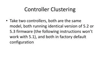
Controller Clustering • Take two controllers, both are the same model, both running identical version of 5.2 or 5.3 firmware (the following instructions won’t work with 5.1), and both in factory default configuration
Controller Clustering • In order for the two controller to cluster together, they need to be able to communicate with each other over an IP session. So, you need to configure a management IP address on each • In factory default configuration, the Ethernet interfaces on the controllers are members of VLAN 1, so let’s configure an IP address for VLAN 1 on each controller
Controller Clustering • On the first controller, let’s configure VLAN 1 with an IP address of 192.168.1.1 Please press Enter to activate this console. br-rfs4000-4F008C login: admin Password: Brocade Mobility Wireless System is currently using the factory default login credentials. Please change the default password to protect from unauthorized access. Enter new password: Confirm new password: Password for user 'admin' changed successfully. Please write this password change to memory(write memory) to be persistent. br-rfs4000-4F008C>en br-rfs4000-4F008C#self Enter configuration commands, one per line. End with CNTL/Z. br-rfs4000-4F008C(config-device-74-8E-F8-4F-00-8C)#int vlan1 br-rfs4000-4F008C(config-device-74-8E-F8-4F-00-8C-if-vlan1)#ip ad 192.168.1.1/24 br-rfs4000-4F008C(config-device-74-8E-F8-4F-00-8C-if-vlan1)#commit br-rfs4000-4F008C(config-device-74-8E-F8-4F-00-8C-if-vlan1)#
Controller Clustering • Next, on the second controller, let’s configure VLAN 1 with an IP address of 192.168.1.2 Please press Enter to activate this console. br-rfs4000-1E1510 login: admin Password: Brocade Mobility Wireless System is currently using the factory default login credentials. Please change the default password to protect from unauthorized access. Enter new password: Confirm new password: Password for user 'admin' changed successfully. Please write this password change to memory(write memory) to be persistent. br-rfs4000-1E1510>en br-rfs4000-1E1510#self Enter configuration commands, one per line. End with CNTL/Z. br-rfs4000-1E1510(config-device-74-8E-F8-1E-15-10)#int vlan1 br-rfs4000-1E1510(config-device-74-8E-F8-1E-15-10-if-vlan1)#ip ad 192.168.1.2/24 br-rfs4000-1E1510(config-device-74-8E-F8-1E-15-10-if-vlan1)#commit br-rfs4000-1E1510(config-device-74-8E-F8-1E-15-10-if-vlan1)#
Controller Clustering • Now, let’s see if one controller can ping the other • In this example, I’m going to ping 192.168.1.2 from my first controller (the controller I just configured with an IP address for VLAN 1 of 192.168.1.1) • Note: If the controllers cannot ping each other, then clustering will not be possible. br-rfs4000-4F008C(config-device-74-8E-F8-4F-00-8C-if-vlan1)#end br-rfs4000-4F008C#ping 192.168.1.2 PING 192.168.1.2 (192.168.1.2): 100 data bytes 108 bytes from 192.168.1.2: seq=0 ttl=64 time=7.187 ms 108 bytes from 192.168.1.2: seq=1 ttl=64 time=0.497 ms 108 bytes from 192.168.1.2: seq=2 ttl=64 time=0.513 ms 108 bytes from 192.168.1.2: seq=3 ttl=64 time=0.481 ms 108 bytes from 192.168.1.2: seq=4 ttl=64 time=0.494 ms --- 192.168.1.2 ping statistics --- 5 packets transmitted, 5 packets received, 0% packet loss round-trip min/avg/max = 0.481/1.834/7.187 ms br-rfs4000-4F008C#
Controller Clustering • Next, pick one of the controllers (it doesn’t matter which one you pick, but just only pick one) and configure a cluster name • In this example, I’m going to pick my first controller (the one with the IP address 192.168.1.1), and configure the cluster name “Linsanity” br-rfs4000-4F008C# br-rfs4000-4F008C#self Enter configuration commands, one per line. End with CNTL/Z. br-rfs4000-4F008C(config-device-74-8E-F8-4F-00-8C)#cluster name Linsanity br-rfs4000-4F008C(config-device-74-8E-F8-4F-00-8C)#commit br-rfs4000-4F008C(config-device-74-8E-F8-4F-00-8C)#
Controller Clustering • And then, go to the other controller and use the join-cluster command to cluster the two controllers together • In this example, I’m going to use the join-cluster command from the second controller (the one with the IP address 192.168.1.2) br-rfs4000-1E1510(config-device-74-8E-F8-1E-15-10-if-vlan1)# br-rfs4000-1E1510(config-device-74-8E-F8-1E-15-10-if-vlan1)#end br-rfs4000-1E1510#join-cluster 192.168.1.1 user "admin" password “(whatever your admin password happens to be)" ... connecting to 192.168.1.1 ... applying cluster configuration ... committing the changes Committed successfully br-rfs4000-1E1510#
Controller Clustering • For this example, my configuration table looks like this:
Controller Clustering • HINT: If you need to know a controller’s Base Ethernet MAC Address you can quickly and easily find it using the “show ver” command on the CLI:
Controller Clustering • From the CLI of the controller that you’ve chosen to be the cluster master (in this example, I’ve chosen Controller 1), enter the following: Navigates you to the config context where you configure the device that you’ve CLI-ed to Navigates you to the config context where you configure interface VLAN 1 Configure VLAN 1 IP Address / Net Mask Navigate back one level Configure the name of the cluster Configure the master priority level to 255 (higher priority number gets to be the cluster master) Configure the IP address of the other controller in this cluster Don’t forget to commit your configuration changes
Controller Clustering • Then, from the CLI of the other controller (the one that you didn’t chose as the cluster master, and in this example I’ve chosen Controller 2), enter the following: Configure the master priority level to 1 (lower priority number means that this controller will not be the master)
Controller Clustering • From the CLI for both controller, enter the command “show running-config” • At the very end of the running-config you will see the device specific configuration (aka: override configuration) for the controller • Here are examples of the device specific configuration (aka: override configuration) from my controllers: From Controller 1: From Controller 2:
Controller Clustering • In this next step, we are going to copy-and-paste each of the device specific (aka override) controller configurations into the other controller’s configuration. • In this example, I’m going to copy Controller 1’s configuration from the running-config and paste it into the CLI for Controller 2 Step 1: Copy from Controller 1 Step 2: Paste into Controller 2 NOTE: You can paste Controller’s 1 configuration into the CLI for Controller 2 from any config context. In this example, I pasted Controller 1’s configuration at the “self” config context for Controller 2. But I could have pasted controller 1’s configuration from any config context.
Controller Clustering • This is what the CLI for controller 2 looks like when you paste the device specific (aka override) configuration from Controller 1:
Controller Clustering • IMPORTANT: Don’t forget to enter the “commit” command after pasting. • If you don’t enter the “commit” command, then the configuration you’ve just pasted will not get applied.
Controller Clustering • And then do the same for Controller 2 • Copy the device specific (aka: override) controller configuration from Controller 2, and paste it into the CLI fro Controller 1 • Important: Don’t forget to enter the “commit” command after pasting the configuration into Controller 1
Controller Clustering • From the CLI for both controller, enter the command “show running-config” • At the very end of the running-config you will see the device specific configuration (aka: override configuration) for the controllers • Here are examples of the device specific configuration (aka: override configuration) from my controllers: • NOTE: Both Controller 1 and Controller 2 should have exactly the same device specific (aka: override) controller configurations
Controller Clustering • Now we are ready to connect the two controllers • Connect them to the same VLAN (i.e. same IP subnet, no router in between) • In reality, controller clustering will also work if there is a router in between, but for this example we are going to keep things simple and put the controllers on the same VLAN
Controller Clustering • After you’ve connected the two controllers, enter this command in the CLI: “show cluster members” • If you enter this “show cluster members” command, and you see something like this: • This means that your two controllers can’t talk to each other. Check your connections to make sure that they are connected to the same Layer 2 network Blank down Blank
Controller Clustering • If you enter this “show cluster members” command, and you see something like this: • This means that the two controllers are talking to each other and trying to decide which controller will be the master in this cluster • This decision (or election process, as it’s called in the CLI) takes less than a minute
Controller Clustering • If you enter this “show cluster members” command, and you see something like this: • Then the controller clustering is complete • Congratulations!