
+-2.7%
2005.07.14 MR/RCS beam commissioning meeting M. Tomizawa. RCS Kicker Field Fluctuation. +-2.7%. +-1%. 2005.6.23 Noda’s mail. RCS キッカーの磁場のゆらぎの影響. RCS exit b x=28.96m, a x=-2.83 ・ +1% fluctuation D x=3.363mm, D x’=0.321mrad ・ -1% fluctuation D x =-3.363mm, D x’ =-0.321mrad

+-2.7%
E N D
Presentation Transcript
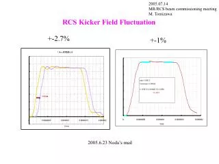
2005.07.14 MR/RCS beam commissioning meeting M. Tomizawa RCS Kicker Field Fluctuation +-2.7% +-1% 2005.6.23 Noda’s mail
RCSキッカーの磁場のゆらぎの影響 RCS exit bx=28.96m, ax=-2.83 ・+1% fluctuation Dx=3.363mm, Dx’=0.321mrad ・-1% fluctuation Dx =-3.363mm, Dx’ =-0.321mrad (Noda’s calculation) ---> ・ +-1% effective emittance growth rate 1.18 54p---> 63.6p Normalized phase space 3-50BT acceptance 120p MR Acceptance 81p 3-50BT/Ring collimator aperture setting 63.6p acceptace/emittance ratio 1.5 --> 1.27
○RCS Second Bunchへの影響は小さい Single bunch 運転は有利(MR h=18) ○Fluctuationによるビームロスが問題 となってきた段階で対策をとる ---> モニターが重要 対策 1. Kicker 改造 2. Additional compensation kicker @RCS or 3-50BT
RCSからのビームのハローが大きい場合の対策 ・(ビーム強度を下げる) ・3-50BTコリメーターのスペックアップ 可能性があるか? 現在 total 450W (1% of full RCS beam) ・放射線の遮蔽 土、地表の線量 ・コリメーターJawの発熱 ・コリメーター周りの放射化とメンテナンス 遮蔽設計、コリメーターの設計 1台(of 12台)で450Wを想定 現実的なロス分布の場合、合計何ワットまで可能か?
12枚 L型12枚 シールド移動型、チェンバー移動型の場合
12-Collimator Jaw: QD-(L-R)-QF-(U-D)-QD2-Catchers: 120pi #73,81 Jaw: tantalum 10cm Incident 120p Jaw set 54p Downstream of catchers: ellipse 72p (Outside/lost 6.3W/450W) Str99_004.com
L型12-Collimator Jaws: QD-(LU-RD)-QF-(LU-RD)-QD 2-Catchers: 120pi, #73, #81 Jaw: tantalum 10cm Incident 120p Jaw set 54p Downstream of catchers: ellipse 58pOutside/lost 6.5W/450W Str99_006.com
L型12-Collimator Jaws: QD-(LU-RD)-QF-(LU-RD)-QD 2-Catchers: 120pi, #73, #81 Jaw: tantalum 10cm Incident 80p Jaw set 54p Downstream of catchers: ellipse 58pOutside/lost 9.7W/450W Str99_006.com
3.6 3-50BT 上部遮蔽構造と隔壁 By 鈴木健訓 隔壁 上部遮蔽構造断面図 平面図 鉄遮蔽体 ケーブル・配管用開口部 通路 開 口 部 断面図 ビームライン平面図 ビームパイプ 断面図 3GeV-P
3.93-50BT スクレーパ損失による遮蔽体表面上の線量評価3.93-50BT スクレーパ損失による遮蔽体表面上の線量評価 By 鈴木健訓 450W 損失 (1)八間道路 一般区域の空間線量率 設計目標値 0.25 μSv/h (1) Emittance 120π 0.055 ± 0.005 μSv/h (2) Emittance 80π 0.050 ± 0.005 (3) 1台 一点損失 0.075 ± 0.005 (No.6) 0.29 ± 0.01(No.12) (2)横方向 土の放射化 設計目標値 1台 11mSv/h, 12台同時 5mSv/h (1) Emittance 120π 1.03 ± 0.01mSv/h (2) Emittance 80π 0.84 ± 0.01 (3) 1台 一点損失 2.31 ± 0.02 (3)床下方向 土の放射化 設計目標値 1台 11mSv/h, 12台同時 5mSv/h (1) Emittance 120π 1.23 ± 0.02 mSv/h (2) Emittance 80π 0.94 ± 0.02 (3) 1台 一点損失 1.53 ± 0.02 八間道路
○ 放射線遮蔽 合計ロス 450Wの 3-4倍はOK ○ Jaw 発熱 60W x 4倍=240W < 450W/1台 ○ コリメーターメンテナンス ・ フランジの遠隔着脱 ・ 被曝を減らす交換シナリオ --> 対策済み 3-4倍は許容できることを期待する(要検討) ○スペックアップする場合はJ-PARC全体のコンセンサスを得る必要がある
MRからのリニアック、RCSへの要求事項 ・リニアックピークビーム強度の可変 (min -> 30mA for 180MeV linac) ・リニアッックマクロパルス長の可変 (min-> 500micro second) ・リニアック中間パルス長の可変 (min->max) ・ペインティングエリアの可変(no painting-> 216pi for 180MeV linac) ・anti-correlated/correlatedペインティングの選択 ・MR行きのバッチ数の可変 (1->4 for h=9) ・MR行きバンチ数1 or 2の選択 ・MR行きの周期の可変 (3s <-> longer) ・MR行きビームのON/OFF 可能な項目・範囲と時期は? 最初はno painting、5mA, 50micro second widthのビーム(10kW)で調整 このビームは結構space chargeがきつくやりにくいのでは?