
Wireless Security System
E N D
Presentation Transcript
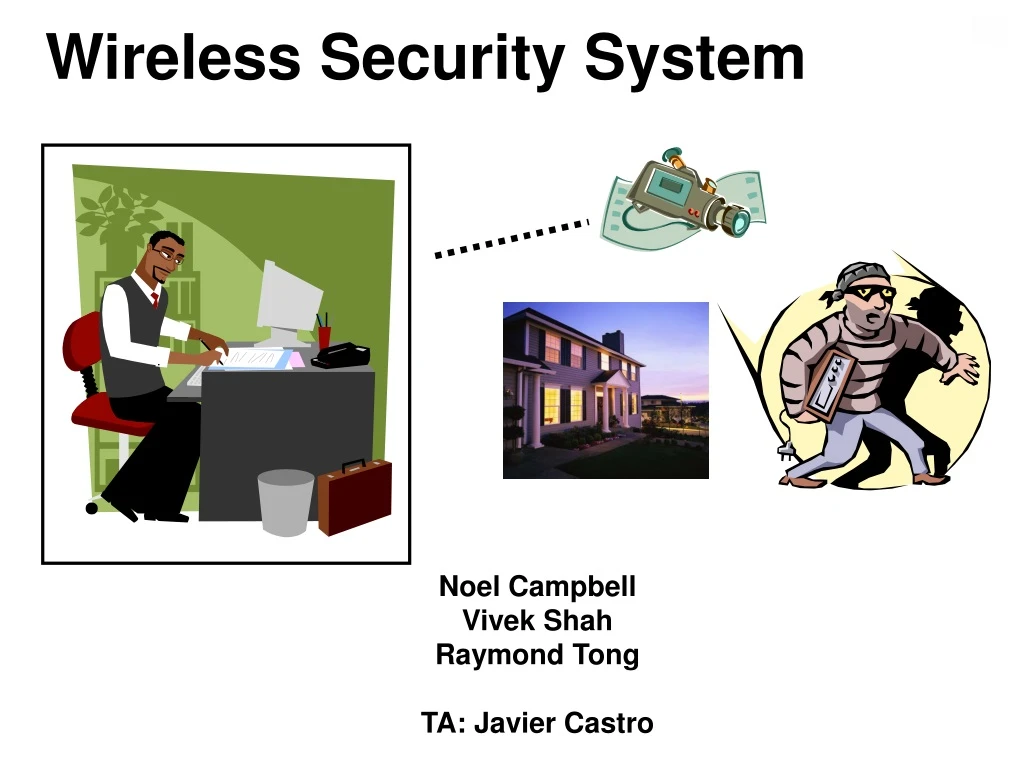
Wireless Security System Noel Campbell Vivek Shah Raymond Tong TA: Javier Castro
Video Capture Overview Y [7:0] Clock_27MHz Y isolator 8 Clock_27MHz WE Dual-Port Block Memory ADV7185 Memory Controller X Camera ADDR Composite In tv_in_ycrcb [19:0] Y 20 ycrcb [29:0] 30 tv_clock encode_busy writing_memory NTSC Decoder Async FIFO RGB YCrCb to RGB Converter Display Syncing and blanking signals Z VGA Controller
Technical Considerations • Synchronization of data • ADV7185 clock vs lab kit 27 MHz clock • Displaying data in VGA • Acquire 240 X 240 real time video • Write data to block memory then continuously read from it • Memory Controller • Write a frame worth of data into block memory for encoding and transmission
Video Compression Discrete Cosine Transform 512 bits/block 56 bits/block Inverse Discrete Cosine Transform
Wireless Transmission • Data is sent serially from the labkit to the wireless kit • Data is assembled into packets and sent from camera-end to fixed-end via CC2420 radio • Data is then sent serially from receiver wireless kit to the receiver labkit
Transmitter from encoder Transmitter Control Unit Radio Transmitter 80 x 900 Dual Port BRAM 80 Shift Register RS232 Sender serial cable 8 toreceiver FPGA microcontroller
Receiver from transmitter Transmitter Control Unit Radio Receiver 80 x 900 Dual Port BRAM 80 RS232 Receiver Shift Register serial cable to decoder microcontroller FPGA
Video Display Overview Clock_27MHz to all modules Y [7:0] RGB Dual-Port Block Memory YCrCb to RGB Converter 8 Display Delay Z Addr X Z Syncing and blanking signals decode_done VGA Controller Memory Controller * Only chrominance (Y) is important if displaying grayscale image