Download
1 / 41
550 likes | 1.36k Views
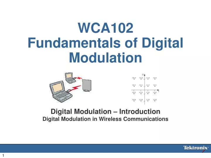
WCA102 Fundamentals of Digital Modulation. Digital Modulation – Introduction Digital Modulation in Wireless Communications. Agenda. Introductions Who Cares? What is Modulation IQ Modulation Types Filters and How Things Go Wrong Measurements. Advantages of Digital Modulation.

E N D
WCA102Fundamentals of Digital Modulation Digital Modulation – IntroductionDigital Modulation in Wireless Communications
Agenda • Introductions • Who Cares? • What is Modulation • IQ Modulation Types • Filters and How Things Go Wrong • Measurements
Advantages of Digital Modulation • Spectral efficiency – use of a narrow bandwidth to send a large amount of data • Effective use of limited frequency resources • Good privacy and security features • Digital encryption techniques may be employed • Lower power consumption • Repeatable, more easily produced • Reduced device size
Modulation for Wireless • Media • Carrier • The 3 essential parameters • Amplitude valueA(t) ― Amplitude Modulation • Frequency valuef(t) ― Frequency Modulation • Phase value φ(t) ― Phase Modulation V(t) = A cos(2πfc t + Φ)
Analog Modulation • Amplitude Modulation • AM radio • Frequency Modulation • FM radio, TV audio signal • Phase Modulation • TV color image signal (including Amplitude Modulation)
Transmission of a Digital Message • Basically, it’s the same as Analog Modulation Methods • ASK: Amplitude shift keying • FSK: Frequency shift keying • PSK: Phase shift keying • Digital modulation: Amplitude, frequency and/or Phase are used to represent a digital state V(t) = A(t) cos(2πfc t + Φ) V(t) = A(t) cos(2πf(t) t + Φ) V(t) = A(t) cos(2πf(t) t + Φ(t))
ASK • Amplitude shift keying • 1’s or 0’s represented by different amplitudes • Could be accomplished with an AM system + =
ASK in IQ domain • ASK(OOK) • I: In phase component • Q: Quadrature component I Q 0 I (1) (0) Q 0 Amplitude variation on I axis
FSK • Frequency shift keying • Select frequency based on each bit, 0 or 1 • Could be done with simple FM system + =
Q I FSK in IQ • Frequency change causes constant-rate phase change versus the reference carrier • Amplitude remains constant on the IQ circle • If the phase change is 90 degrees in one symbol period, the modulation type is called Minimum Shift Keying (remember this one) Phase 1 Symbol only turns π(ex) π Time 1Sp 2Sp 3Sp 4Sp 5Sp -π Pos offset Neg. Offset Pos. Offset
PSK • Phase shift keying • At the bit transitions invert the phase by 180° = +
Representation of PSK in IQ • PSK • Specifically, BPSK(Binary Phase Shift Keying) I Q 0 (1) I (0) Q 0 Change Phase to 180° Relative to reference
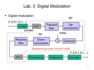
I - Signal Modulation, Upconversion RF Amplifier Q - Signal Digital Modulation Block Diagram Convert to Symbols Raw Data 011010100101 Compression, Error Correction, Encryption 011010100101 110101 I - Signal 01 00 Low Pass Filter To IQ Modulator Q - Signal Low Pass Filter 11 10 Modulation Mapping
Raw Data Compression, Error Correction, Interleaving, Encryption 011010100101 110101 Raw Data Conversion • Raw data comes from the user • Digitized voice, keystrokes, jpegs… • Compression is employed for efficiency • Error correction is applied for transmission quality • Interleaving creates signal-dropout resistance • Encryption is applied for security Convert to Symbols
Raw Data Compression, Error Correction, Encryption 011010100101 110101 Data Bits, to Symbols • Symbols are represented by the possible states of digital modulation • Higher order modulation allows more bits per symbol • What in the world does that mean? • Mapping symbols to I and Q Convert to Symbols 011010100101
What is Mapping: Translate a Symbol to a point in the IQ space Example 01 00 11 10 Modulation Mapping IQ Mapping Q (01) (11) I (00) (10)
QPSK(Quadrature PSK) Assign the value to points inIQ Space DQPSK(Differential QPSK) The value is based on the transitions between 2 points Q (01) (11) I (00) (10) Differential Modulation Q (01) (00) I (11) (10) 00= 0 01= +90 10= -90 11= +180
8PSK(8-PSK) Assign the value to points inIQ Space 3 points per symbol p/4 DQPSK The value is based on the transitions between 2 points Eliminates Zero Crossings Higher Order Modulation Q Q (110) (11) (001) (011) (00) (01) (111) I I (100) (10) (000) (010) (101) 00= -45 01= +135 10= -135 11= +45
16QAM(16-Quadrature Amplitude Modulation) Each IQ symbol location is represented by 4 data bits 64QAM (64-Quadrature Amplitude Modulation) Each symbol is now worth 5 bits Q (0010) (0110) (1110) (1010) (0011) (0111) (1111) (1011) I (0001) (0101) (1101) (1001) (0000) (0100) (1100) (1000) More Higher Order Modulation Q (000100) (001100) (011100) (010100) (110100) (111100) (101100) (100100) (000101) (001101) (011101) (010101) (110101) (111101) (101101) (100101) (000111) (001111) (011111) (010111) (110111) (111111) (101111) (100111) I (000110) (001110) (011110) (010110) (110110) (111110) (101110) (100110) (000010) (001010) (011010) (010010) (110010) (111010) (101010) (100010) (000011) (001011) (011011) (010011) (110011) (111011) (101011) (100011) (000001) (001001) (011001) (010001) (110001) (111001) (101001) (100001) (001000) (011000) (010000) (110000) (111000) (101000) (100000) (000000)
Errors in IQ modulation create symbol errors in transmission Vector Errors are created (what’s that?) Noise in the transmission channel create symbol errors Inaccuracies in the receiver creates errors Signal-to-noise requirements increase with higher order modulations Q Q (01) (11) (0010) (0110) (1110) (1010) (0011) (0111) (1111) (1011) I I (0001) (0101) (1101) (1001) (00) (10) (0000) (0100) (1100) (1000) Why Not Just Keep Going?
The World’s Most Popular Modulation • Gaussian Minimum Shift Keying • Gaussian Filtered Form of FSK • Sum of I and Q results in a constant amplitude circle
Symbol Rate and Bit Rate • Modulation type determines number of bits per symbol • BPSK 1 bit/symbol • DBPSK 1 bit/symbol • QPSK 2 bit/symbol • p/4 DQPSK 2 bit/symbol • DQPSK 2 bit/symbol • 8PSK 3 bit/symbol • 16QAM 4 bit/symbol • 64QAM 5 bit/symbol • 256QAM 6 bit/symbol • For a fixed symbol rate, having more bits will provide a faster transfer rate • Setting up a WCA requires you to know the modulation type and symbol rate, not the bit rate
32QAM ADSL etc 256QAM Microwave Communication Some Cable Modem 1024QAM Still experimental OQPSK Offset QPSK Used to avoid zero crossings DQPSK HPSK Hybrid Phase Shift Keying Also known as Orthogonal Complex Quadrature Phase Shift Keying (OCQPSK) Used in CDMA2000 (1xRTT) reverse link VSB Vestigial Side Band 8VSB, 16VSB US Digital Broadcast TV Others (for evening reading….)
I - Signal 01 00 Low Pass Filter To IQ Modulator Q - Signal Low Pass Filter 11 10 Modulation Mapping Filters, For Spectrum Control
Convert to Symbols Raw Data 011010100101 Compression, Error Correction, Encryption 011010100101 110101 I - Signal 01 00 Low Pass Filter To IQ Modulator Q - Signal Low Pass Filter 11 10 Modulation Mapping I - Signal Modulation, Upconversion RF Amplifier Q - Signal Sources of Error
Sources of Error • IQ Quadrature modulation cos(2πfct) I LPF fc BPF 90 90 90° LPF Q sin(2πfct)
cos(2πfct) LPF I 90 fc BPF 90 90° LPF Q sin(2πfct) Errors Receiving the Signal • IQ Quadrature demodulation • This could be your customers receiver, or it could be a WCA vector spectrum analyzer
What data was sent? • Data Display • Time vs. Amplitude • Error Summary
Error Summary • Error Vector Magnitude • Magnitude and Phase Error • Freq. Error • IQ offset
Modulation Errors vs. Time • Amplitude errors correlated to EVM • WCA is especially good at this
Modulation types Symbol rates Filter types One button setups Standards What can a WCA do?
Summary • Digital modulation is cheaper, faster, more accurate, more efficient, more secure • Higher order modulation is used for greater transmission rates in the same spectrum occupancy • Higher order modulation is more susceptible to noise • Baseband filters are used to control spectrum • Wireless Communications Analyzers are used to evaluate modulation quality • WCA is particularly good at connecting effects in multiple domains
Dedicated Regional Contacts Kurt Krukenbergphone: +1 503-627-5039Regional Product Manager Americas Dean Milesphone: +44 1344-392249Regional Product ManagerEMEA Charles Wuphone: +852 258-56774Product Line RepresentativeAsia/PacRim Worldwide Factory Contacts Dave McDonaldphone: +1 503-627-1279 TSC Primary Contact WCA200A and WCA300 Tommy Sakuradaphone: +81 3-3448-3272Product ManagerWCA200A & Wireless Apps Jerry Harrisphone: +1 503-627-4827Product Manager WCA300 & Non-Wireless Apps Product Line Contact Information
I - Signal 01 00 Low Pass Filter To IQ Modulator Q - Signal Low Pass Filter 11 10 Modulation Mapping Filters Alter The Signal
Gaussian Raised Cosine Root Raised Cosine Setting up the WCA requires knowledge of what filter is used Common Filter Types
Usually α is between 0.2 - 0.5 α determines the bandwidth Effect of Roll-off α=0.0 α=1.0 BW = (1+α) *Symbol rate
PutIQ on the Carrier Wave • IQ Quadrature modulation cos(2πfct) I LPF fc BPF 90 90 90° LPF Q sin(2πfct)
Structure of Tx/Rx Encode Scrambling Error correction encoding Interleaving 1st Interleaving 2nd Datastream IQ mapping IQ modulation IQ demodulation IQ de-mapping De-interleaving 2nd De-interleaving 1st Error correction decoding Scrambling Datastream