Download
1 / 31
330 likes | 748 Views
MULTILEVEL GRID-CONNECTED INVERTER PERFORMANCE UNDER DIFFERENT MODULATION STRATEGIES. Mohan V. Aware. Jayant J. Mane. Visvesvaraya National Institute of Technology, Nagpur, India.

E N D
MULTILEVEL GRID-CONNECTED INVERTER PERFORMANCE UNDER DIFFERENT MODULATION STRATEGIES. Mohan V. Aware. Jayant J. Mane. Visvesvaraya National Institute of Technology, Nagpur, India.
Fig. 1. A Schematic diagram showing the distributed generation and its connection to grid through multilevel inverter.
Fig. 2. (a) Diode Clamped Three-level inverter. (b) Modulation signal, carrier signal, Gate pulses generated with SPWM (Ma=0.8, fs=2kHz) for Three-level inverter.
Table I. Diode-Clamped Three- Level Converter VoltageLevels and Their Switch States.
Fig. 3. (a) Diode Clamped Five-level inverter. (b) Modulation signal, carrier signal, Gate pulses generated with SPWM (Ma=0.8, fs=2 kHz) for Five-level inverter.
Table II. Diode-Clamped Five- Level Converter VoltageLevels and Their Switch States.
Fig. 4. Three phase sinusoidal pulse width modulation signal.
Fig. 5. Three phase space vector pulse width modulation signal
Fig. 6. Three phase Depenbrock’s pulse width modulation signal.
Fig. 7 Nature of Output Phase Voltage (a) Two Level Inverter. (b) Three Level Inverter. (c) Five Level Inverter.
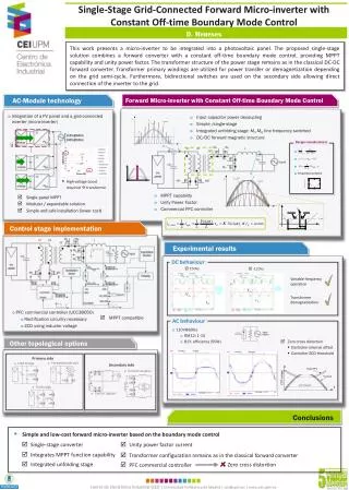
Simulation wave forms (from top - Phase voltages, line voltages and line currents) with DPWM1 for five level inverter. (Ma = 0.8, fs=2 kHz, 3-phase star-connected load with power factor 0.8)
Two Level Inverter % Total Harmonic Distortion in Line-to-Line Voltage.
Three Level Inverter % Total Harmonic Distortion in Line-to-Line Voltage.
Five Level Inverter % Total Harmonic Distortion in Line-to-Line Voltage.
CONCLUSION The SVPWM control is observed to be a better with respect to other two control strategies. The THD in three level and five level inverters are 24% and 12% as compared to 52% in two level for a SVPWM control strategy.
REFERENCES [1] Jih-Sheng Lai and Fang Zheng Peng “Multilevel Converters-A New Breed of Power Converters”. IEEE Transactions on Industry Applications, Vol. 32, No. 3,May/June 1996 [2] Fang Zheng Peng. “A Generalized Multilevel Inverter Topology with Self Voltage Balancing.” IEEE Transactions on Industrial Applications, VOL. 37, NO. 2, March/April 2001 [3] Jose Rodriguez, Steffen Bernet, Peter K. Steimer, and Ignacio E. Lizama. “A Survey on Neutral-Point-Clamped Inverters” IEEE Transactions on Industrial Electronics, VOL. 57, NO. 7, July 2010. [4] Brendan Peter Mcgrath and Donald Grahame Holmes,”Multicarrier PWM Strategies for Multilevel Inverters”. IEEE Transactions on Industrial Electronics, VOL. 49, NO. 4, August 2002 [5] Ahmet M. Hava, Russel J. Kerkman and Thomas A. Lipo “Carrier-Based PWM-VSI Overmodulation Strategies: Analysis, Comparison, and Design” IEEE Transactions on Power Electronics, VOL. 13, NO. 4, July1998. [6] José Rodríguez, Jih-Sheng Lai and Fang Zheng Peng. “Multilevel Inverters: A Survey of Topologies, Controls, and Applications”. IEEE Transactions on Industrial Electronics, Vol. 49, No. 4, August 2002 [7] Haitham Abu-Rub, Joachim Holtz, Jose Rodriguez and Ge Baoming. “Medium-Voltage Multilevel Converters—State Of The Art, Challenges, And Requirements in Industrial Applications”. IEEE Transactions on Industrial Electronics, Vol. 57, No. 8, August 2010 [8] Leon M. Tolbert and Thomas G. Habetler. “Novel Multilevel Inverter Carrier-Based PWM Method”. IEEE Transactions on Industry Applications, Vol. 35, No. 5, September/October 1999 [9] Bor-Ren Lin. “Analysis and Implementation of a Three-Level PWM Rectifier/Inverter”. IEEE Transactions on Aerospace and Electronic Systems Vol. 36, No. 3 July 2000. [10] B.Urmila, D.Subbarayudu. “Multilevel Inverters: A Comparative Study of Pulse Width Modulation Techniques”. International Journal of Scientific & Engineering Research, Volume 1, Issue 3, December-2010. [11] Won-Sik Oh, Sang-Kyoo Han, Seong-Wook Choi and Gun-Woo Moon. “Three Phase Three-Level PWM Switched Voltage Source Inverter with Zero Neutral Point Potential”. IEEE Transactions on Power Electronics, Vol. 21, No. 5, September 2006. [12] Mingyan Wang and Kai Tian. “A Nine-Switch Three-Level Inverter for Electric Vehicle Applications”. IEEE Vehicle Power and Propulsion Conference (VPPC), September 3-5, 2008, Harbin, China. [13] C.Newton and M.Sumner. “Novel Technique for Maintaining Balanced Internal DC Link Voltages in Diode Clamped Five-Level Inverters”. IEEE Proc.-Electr. Power Appl., Vol. 146, No. 3, May 1999. [14] John A. Houldsworth and Duncan A. Grant. “The Use of Harmonic Distortion to Increase the Output Voltage of a Three-Phase PWM Inverter”. IEEE Transactions on Industry Applications, Vol. Ia-20, No. 5, September/October 1984. [15] Chunmei Feng Vassilios G. Agelidis. “On The Comparison of Fundamental and High Frequency Carrier-Based PWM Techniques for Multilevel NPC Inverters”. 2002 IEEE
REFERENCES continued…….. [16] Jang-Hwan Kim, Seung-KiSul, Hyosung Kim, and Jun-KeunJi. “A PWM Strategy for Four-Leg Voltage Source Converters And Applications To A Novel Line Interactive UPS in A Three-Phase Four-Wire System”. IAS 2004. [17] P.K. Chaturvedi1 S. Jain P. Agarwal. “Reduced Switching Loss Pulse Width Modulation Technique for Three-Level Diode Clamped Inverter”. IET Power Electron. 2011, Vol. 4, Iss. 4, Pp. 393–399 [18] B. Kaku, I. Miyashita, Ssone. “Switching Loss Minised Space Vector PWM Method for IGBT Three Level Inverter.” IEE Proc.-Electr. Power Appl., Vol. 144, No. 3, May 1997. [19] H. Radermacher B. D. Schmidt R.W. De Doncker. “Determination and Comparison of Losses of Single Phase Multi-Level Inverters with Symmetric Supply”. 35lh Annual IEEE Power Electronics Specialists Conference Aachen. Germany, 2004.