Download
1 / 51
510 likes | 629 Views
Scalable, Robust Wide-area Control Architecture for Integrated Communications. Helen J. Wang Qualifying Examination March 8, 2000. Cellular. Pager. PSTN. Internet. Motivation. Lack support for: Integrated use of heterogeneous devices (old & new)

E N D
Scalable, Robust Wide-area Control Architecture for Integrated Communications Helen J. Wang Qualifying Examination March 8, 2000
Cellular Pager PSTN Internet Motivation • Lack support for: • Integrated use of heterogeneous devices (old & new) • Rapid arbitrary communication service customization
Limitations of Existing Systems • Telecommunications network: • engineered with one app and device in mind • Existing Internet Telephony systems: • ease of service creation, but limited • scalability, availability and fault tolerance not fully addressed
How good is a communication system?(Dissertation Goals) • Functionality: communication services it can support, and the ease of creating them • Viability: scalability, robustness • Focus on the control aspect: • control architecture = system components + signaling protocol (session setup, tear-down, and control)
Problem Statement • Given heterogeneity, how to design a scalable, robust wide-area control architecture that supports easy creation of a wide range of communication services? And how should these services be created?
Outline • Related Work and Research Contribution • Control Architecture • Signaling Protocol • Service Creation Model • Summary, Methodology, Research Agenda
Overview of Research Contributions • A scalable control architecture • A robust signaling protocol • A user-level, easy service creation model • Publications: • “A Signaling System Using Light Weight Sessions” accepted to Infocom 2000. • Helen J. Wang, et al. “ICEBERG, An Internet-Core Network Architecture for Integrated Communications,”accepted to IEEE Personal Communications April/2000.
Outline • Related Work and Research Contribution • Control Architecture • Signaling Protocol • Service Creation Model • Summary, Methodology, Research Agenda
Control Architecture: Goals • Any-to-any communication • inter-working, composition of data transformation • Personal mobility • unique ID, name mapping • Personalized communication services • preference storage and management • Enable user-activity driven services • activity tracking
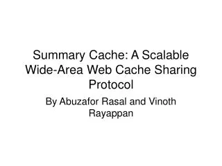
iPOP Call Agent iPOP IAP Call Agent dialed 333-2222 IAP PR NMS PR NMS APC APC PAC PAC Control ArchitectureComponents and Their Operations Alice@domain1 Bob@domain2 Pick up Data Path
Leverage Cluster Computing Platforms • iPOP must be scalable and robust: leverage cluster computing platforms such asNinja, AS1 • Our requirements: • highly available service invocation: Ninja Base • fault tolerant service session: AS1 • session state maintained on client (IAP) • iPOP on Ninja Base augmented with client heartbeat support from AS1
iPOP iPOP Control Architecture:Facts Access net Call Agent Call Agent IAP PR PAC PR PAC Local area communication Wide-area communication • One Call Agent per caller per device • One type of IAP per access network
Outline • Related Work and Research Contribution • Control Architecture • Signaling Protocol • Service Creation Model • Summary, Research Methodology, Agenda
Signaling Protocol • Basic call service: building blocks for supplementary services • Conventional: two party, homogeneous devices • ICEBERG communication model: • multi-device communication • invitation-based participation • large number of dynamic small group communication • Richer primitives: add/remove an endpt during a session • conference call, service handoff first class service; trivial to implement services that require endpoint changes.
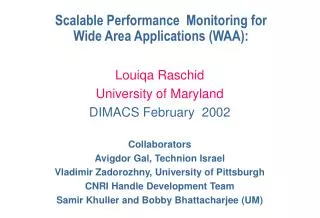
Alice Bob Carol Alice Bob Dale CA3 CA4 Carol Dale Invite Bob Invite Alice Invite (also Bob) Invite (also Alice) Alice Alice Bob Bob Challenges in Signaling:Problems with SIP CA1 CA2 CA5 Alice Bob Carol Dale Dale Carol • no consideration of session dynamics: membership, component failure • bridged conference: centralized component to maintain states -- single point of failure
Problems with H.323 • Centralized approach for conferencing • Limited fault tolerance measure: • process-pair style • cannot capture new state during fault recovery • Complex
Lessons Learned • Correctness and robustness: • need to maintain up-to-date membership and session state (call parties, device status, data path info) in the face of transient component failures, network partitions, and any exceptional conditions. • distributed approach rather than centralized
Our Approach • Maintain membership and session state as soft state in a distributed fashion. • Soft state: expired unless refreshed, protocol action upon new state or timeout, error recovery same as normal operation • Question: call setup latency requirement? bandwidth scalability problems?
Signaling Protocol: Session Membership • Session membership • membership: CAs • IP multicast’s group service an overkill for small group communication • per group state in routers, IP addr scarcity, deployment issues: access control, accountability • Solution: run an application-level group membership protocol among participating IAPs
Announce Announce Listen Listen APC APC Announce Listen HB HB iPOP HB iPOP HB HB APC Signaling Protocol: Capture the Complete Session State Call Agent Call Agent Session state Session state Comm Session iPOP iPOP IAP IAP Call Agent Session state IAP iPOP iPOP HB
Announce Announce Listen Listen Announce Listen HB HB iPOP HB iPOP HB Call Agent Session state HB Signaling Protocol: Fault Tolerance Call Agent Call Agent Session state Session state Comm Session APC APC iPOP iPOP IAP IAP IAP APC iPOP iPOP HB
Announce Announce Listen Listen Announce Listen HB HB iPOP HB iPOP HB Call Agent Session state HB APC iPOP iPOP HB Signaling Protocol: Fault Tolerance Call Agent Call Agent Session state Session state Comm Session APC APC iPOP iPOP IAP IAP IAP
Announce Announce Listen Listen HB HB iPOP HB iPOP HB iPOP Signaling Protocol: Fault Tolerance Call Agent Call Agent Session state Session state Comm Session APC APC iPOP iPOP IAP IAP IAP APC
Invitation Protocol • Invite a Call Agent to participate a session • Also a soft state protocol for robustness: • IAP maintains the call state machine, sends stateful, keep-alive heartbeat to the iPOP • Call Agents advance call state machines on IAPs through periodic install-state message until receiving new heartbeat with the new state • Soft state inter-iPOP communication
Bandwidth Scalability • Soft state period selection: call setup latency, fault recovery time vs Bandwidth overhead • An optimization problem: minimize bandwidth overhead, subject to the following contraints: • expected call setup latency (1.5 second) • standard deviation (0.5 second) • fault recovery time (1, 4 seconds for local and wide area) • parameters: 2% wide-area loss rate, 0.2% local-area loss rate, 2ms local-area propagation delay, 100 ms wide-area delay • local: 1 sec, 800bps; wide: 3 sec, 233 bps; for 64kbps data stream, local area control traffic 1%
Processing Scalability • Compare our single cluster system against a class 4 switch which is a local (end) office: 250 calls/second • Our current prototype yields 10 calls/second on a PC due to inefficient RMI implementation (10’s ms), 25+ PCs = a class 4 switch
Outline • Related Work and Research Contribution • Control Architecture • Signaling Protocol • Service Creation Model • Research Agenda
Service Creation Model • Focus: control, redirection services • Goal: end users can easily customize the control services in any arbitrary way • Issues: • service creation/customization • service invocation • service portability • system support
Intelligent Network • Separate service logic from basic call processing Switch Service Logic Trigger • Service portability: standardize basic call state machine too strict a standard failed • Limitation: no user-level customization
Proposed Approach • Call processing implementation independent customization: use high-level events, e.g., call request received, callee device busy, callee device not answer • Service creation: condition-action pairs • condition: conjunction of high level events, user interested conditions, and boolean expressions; • Action: composition of system primitives • Hypothesis: condition-action pair sufficient
check update Activity Condition Action event Condition Action Proposed ApproachService Invocation & Portability • Service Portability: standardize the events and system primitives, much easier than call state machine Preference Registry Call Agent PAC Condition Action Condition Action
An ExampleCompletion of calls to busy subscriber callee busy && caller hang up register with callee PAC; callee PAC reject exit callee PAC notify invite caller; invite callee; caller busy wait 5 minutes; re-register with the callee PAC; hangup time > 1 hours de-register with callee PAC; exit
An Example, Cont. • System support issues: • extended Call Agent life time • queue management on the PAC • track event sequence: stack of timed events, stack depth depending on user preferences
How good is a communication system? • Functionality: services • component identification • powerful signaling protocol primitives • easy, user-centric service creation model • Viability: scalability, robustness • first application of soft state to signaling protocol, bandwidth overhead not an issue, can fulfill latency requirements • processing scalability, local area robustness by leveraging cluster computing platforms
Outline • Related Work and Research Contribution • Control Architecture • Signaling Protocol • Service Platform • Methodology and Research Agenda
Methodology1st Iteration (Completed) • Control architecture • Session maintenance protocol • Control architecture • Signaling protocol • session maintenance protocol Design Prototype Analysis Evaluation • Measured the current prototype • Simple soft state period analysis
Methodology2nd Iteration Overview • Wide-area testbed • Group membership protocol • Invitation protocol • Service creation model • Service creation model • Possibly revise the design of the control architecture and the signaling protocol • Completed work: • invitation protocol • membership protocol Design Prototype Analysis Evaluation • Evaluation: scalability, robustness, service creation, hard/soft state comparison • Analysis: group membership protocol, service creation
Research Agenda • Phase 1: complete and fine-tune service creation model design (1 month) • define events and system primitives • preference conflict resolution • identify service creation interaction with the control architecture and signaling Planned paper submission on service creation model design to SmartNet 3/31
Research Agenda • Phase 2: 2nd iteration Prototyping (3 - 6 months) • invitation protocol, membership protocol • employ Ninja vSpace • release ICEBERG to Ericsson, TU Berlin, NTT and construct a wide-area test-bed • service creation model Planned paper submission to ICNP (May) or INFOCOM (July) on protocols and analysis
Research Agenda, Cont. • Phase 3: Evaluation (6 months) • processing scalability: measure call processing time, # of simultaneous sessions, compare against class 4 switch • bandwidth scalability: group membership protocol analysis; dynamic soft state period selection • robustness: emulate failure conditions (losses, long delays, component failures), run system over time • hard/soft state comparison: bandwidth usage, latency, fault recovery time
Research Agenda, Cont. • Service creation evaluation: • comparable functionality : implement representative IN services such as “call completion upon busy” • new services such as policy-based call waiting • system extensibility: # of lines of code and amount of time to develop new primitives for new services Planned paper submission on wide-area testbed experience and evaluation to SIGMETRICS 3/2001
Research Agenda, Cont. • Phase 4: Write thesis (6 month) • compile the publications
Acronyms Lookup • APC: Automatic Path Creation • CA: Call Agent • IAP: ICEBERG Access Point • iPOP: ICEBERG Point of Presence • NMS: Name Mapping Service • PAC: Personal Activity Coordinator • PR: Preference Registry
Soft State expire unless refreshed, protocol action upon new state and timeout loss of state will not stop the system -- robust eventual consistency error recovery built into normal operation --simple, but longer latency, and no diagnosis Hard State explicit state setup once only (bandwidth and processing efficiency) explicit error detection and recovery synchronously at involved components -- complex but immediate better consistency guarantees Soft and Hard State
Signaling Protocol: Group Membership Protocol • Periodic membership exchange among members • no bootstrapping needed: every member knows at least one other member (invitation-based) • receive superset or disjoint set: immediate synchronization with the rest of the session • run among the IAPs for Call Agent fault recovery • time stamped <IAP, CA> list • Convergence efficiency rather than bandwidth efficiency
Period Selection • Soft State Period: dominates fault recovery time, affects bandwidth overhead • cannot trade latency for bandwidth scalability • Problem: what period values to select to fulfill the call setup latency, fault recovery latency requirements and minimize the bandwidth overhead? -- an optimization problem
Select PeriodProblem Formulation • Call setup latency = receiving 8 local-area and 4 wide-area msgs in sequence + msg processing time • Receive a local-area msg = f (local-area period, local-area loss-rate, local-area propagation delay) • The optimization problem: • find local-area and wide-area period that minimize bandwidth overhead, subject to the following constraints • E(call setup latency) <1.5 second • Standard deviation (call setup latency) < 0.5 second • local-area fault recovery time <1 s; wide < 4 s • with parameters: 2% wide-area loss rate, 0.2% local-area loss rate, 2ms local-area propagation delay, 100 ms wide-area delay
Results: Period = f (processing) • fault recovery time constraints dominate the effects on period • local-area period = 1s • 800 bps overhead • wide-area period = 3s • 233 bps overhead • for 64kbps data stream, 1% * # of members
Preference Registry Condition Action Proposed Approach: Service Creation • Condition: conjunction of high level events, user interested conditions, and boolean expressions; • Action: sequence of system primitives • Advantage: call processing impl. independent • Hypothesis: condition-action pair sufficient Call Agent GUI User