Combined Selective Systems :-
Combined Selective Systems :-. Combined Selective Systems :-. Double Ended Unit Substations :-. One-Line Diagrams:-. Introduction. Chapter 3 (protection of industrial power system). Lecture 3 Chapter 3 (protection of industrial power system) Current and voltage Transformers:-
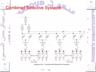

Combined Selective Systems :-
E N D
Presentation Transcript
One-Line Diagrams:- Introduction
Chapter 3 (protection of industrial power system) Lecture 3 Chapter 3 (protection of industrial power system) Current and voltage Transformers:- Current Transformer: It is a device produces a primary current at a reduced level . A current transformer (CT) designed for measuring purposes operates over a range of current up to a specific rated value (circuit normal rating ) and it has a specified errors at that value . On the other hand a protection CT is required to operate over a range of current many times the circuit rating . Under such condition, the flax density corresponds to advanced saturation and the response during this and the initial transient period of short circuit current is important . Thus the method specifying measuring CT is not necessarily satisfactory for those for protection , and a deep detail of knowledge of CT operation is required to predict the performance of the protection
CT's have two important qualities: 1-CTs reduce primary current to a value which can be carried by a small cross sectional area cable to suit protection and measuring circuit. 2-They provide insulation berried for protection used for the high voltage equipment. Construction: Fig. 3.1 Construction of a current transformer
Design: * CTs based on the normal transformer e.m.f equation where the average induced voltage is equal to the product of the number of turns and the rate of change of magnetic flux (Ф)=F/R. The normal design citation is to limit the flux to the value where saturation commencer (known as the knee point flux) and therefore it is the maximum value of the magnetizing current which produces this flux. *Magnetizing current charges from zero to maximum in 1/4 cycle and therefore the rate of change of flux is {(Ф-0)/(1/4)}=4 Ф web/cycle * Or at a frequency of cycle/sec Flux=4 Фf web/sec But Li=N Ф=Var * Thus the induced voltage Var= 4 ФfN where N=Number of turns
At knee point voltage Vr.m.s = 1.11 Var Vr.m.s= 1.11*4 Ф f N = 4.44 Ф f N * In terms of flux density Vr.m.s = 4.44 f N B*A Example: The flux density of electrical sheet steel is about 1.5 tesla (web/m^2) at knee-point of CT ratio 300/1 with core area of 40*30mm^2. Determine the knee point flux. Solution: B= Ф/A or Ф=B*A = 1.5*40*30*10^-6=.0018 web on f=50Hz The knee point voltage=4.44*0.0018*300*50=120v
Short time factor Short time factor : CTs which are used in power system are subjected to fault currents many times their rated current, and therefore, they must be able to withstand the effect of this current for short time. The maximum current which it can carry without mechanical and thermal damage is expressed as multiple of its rated short time factor. Burden : The load of current transformer is called the burden and can be expressed either as a VA load or as impedance.
Burden For example : A 5 VA burden on a 1A current transformer would have an impedance : Or on a 5A CT
A ring – type CT as shown in fig ( 3.2 ) is of secondary winding resistance (RL) , magnetizing current (Ie) and resistance (Rb) and reactance ( Xb) burden . The primary turns must be equal the secondary and magnetizing Ampere- turns, so, N1 I1 = N2 ( I2 + Ie) In practice Ie very small compared with I2 and is ignored in all CT calculation with the except of those concerned with ratio and phase angle error. By ohm law V2 = I2 (R2 + Rb + jxb)
The ratio error The ratio error : which is the difference in magnitude of I1 & I2, and Ө which the phase angle error are apparent as shown in Fig 3.3. Magnetizing characteristic for 100/1 A CT is shown in Fig 3.4 and it is measured before that Ie is small compared to I2 up to and beyond the knee-point of the characteristic. Hence the ratio and phase angle errors will also be small. Fig. 3.4 CT magnetizing characteristic
The ratio error This means that the primary / secondary current relationship will be maintained to this point. These If I2 (R2 + Rb + jXb) = 120 V = V knee And if R2 = 1 Ω Rb + jXb = 7.5 + j0 Ω Then linearity would be maintained up to a secondary current of I2 = 120 / 8.5 = 14.1 A *
CT rating CT rating : Alternatively, if linearity is required up to 20 * CT rating, then the total impedance should not exceed R2 + Rb + jXb = 120 / (20 * 1) =6 Ω For example: CT of ratio 200/5, which is capable of withstanding 13000A would have a short time factor of 65 such factor would be associated with a period of duration of the current ( 3 seconds ). Smaller current would be permissible for long time.
Accuracy Limit Factor * CT used for protection should maintain its characteristic ratio up to some multiple of its rated current. This multiple could be 10, 20, or higher and it is known as (Accuracy Limit Factor). • In case of measuring CTs, the small ratio error is often compensated by modifying the ratio of the primary to secondary turns from the nominal ratio. For example a 100/1A CT might have one primary turn and 98 secondary turns, so the transformation ratio would be 100 to * But it is used to supply protective relay, more burden is applied and therefore the secondary current is reduced to 1 Amp by the magnetizing losses.