Download
1 / 69
700 likes | 863 Views
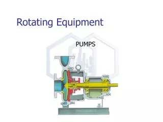
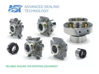
RELIABLE SEALING FOR ROTATING EQUIPMENT. The packed stuffing box.

E N D
The packed stuffing box Before mechanical seals, the attempts to control leakage of product around reciprocating or rotating shafts meant restricting the shaft and stuffing box wall clearance. This was accomplished by packing a soft, resilient material around the shaft in what is typically referred to as a stuffing box. Compression packings, referred to as mechanical packings, are still used in many applications because of their low initial cost, availability, familiarity, and ease of installation.
The packed stuffing box However, there are issues with mechanical packings. They can be expensive to maintain and in some cases result in excessive product losses to the environment. This high potential expense is often the result of improper packing installation or poor equipment condition. But the fact still remains with few exceptions, all packings must leak to work properly. They may leak flush water or they may leak product, but they still leak. This is the number one reason why mechanical packings are being replaced by mechanical seals. Another problem with mechanical packings is that they will cause shaft or sleeve damage given enough time. Even the newer materials will eventually wear the shaft or sleeve.
The purpose of a mechanical seal Mechanical seals were developed to address the disadvantages of and problems with compression packings. The purpose of a mechanical seal is to reduce, or in most cases eliminate, leakage of product or other fluids to the environment. A mechanical seal consists of two extremely flat seal faces, held together by product pressure and spring force to prevent product from escaping to the environment. Visible leakage that comes from compression packing is usually eliminated. Non-visible leakage (i.e., fugitive emissions) is often reduced by mechanical seals in order to meet the environmental laws of local, state, and federal regulatory agencies. Compression packings just cannot be used to comply with these environmental laws.
The purpose of a mechanical seal Mechanical seals applied correctly can reduce the operating and maintenance costs of most plants. However, a higher level of training is required for engineering and maintenance personnel to ensure mechanical seal reliability. It is important to note that initial installation costs for seals may be higher than compression packings. It is also important to realize increasing system reliability means that mechanical seals must be applied correctly and that some applications may require custom seals.
Mechanical seal components: seal rings The seal rings are a pair of parts with extremely flat mating surfaces held together by process and spring pressure to prevent product from escaping. In a mechanical seal, one ring rotates with the shaft while the other ring remains stationary.
Mechanical seal components: secondary seals All mechanical seals will use some type of secondary sealing device to eliminate leakage at all other areas outside the seal rings. The two main places secondary seals are used is between the mechanical seal and the pump shaft and between the seal gland and pump seal chamber face. Secondary seals may be O-rings, gaskets, U-cups, wedges, rubber bellows, metal bellows, or other forms.
Mechanical seal components: metal parts Mechanical seals also have plenty of metal hardware. Typical hardware may include the following, just to name a few: shaft sleeves, gland rings, set screws, collars, compression rings, pins, springs, bellows, drive lugs, snap rings, and more.
Seal rings The seal rings have two extremely flat faces held together by process and spring pressure to prevent product from escaping. The seal rings may be of dissimilar materials, one harder than the other, or both may be hard materials. The seal ring with the narrow face is called the primary ring, and the other is called the mating ring. If dissimilar materials are used, the narrow primary ring is the softer material. As the narrow, softer face wears on the seal ring, it maintains contact with the harder face throughout the life of the mechanical seal. The narrow primary face can be on either the rotating or stationary seal ring.
Secondary seals: gland seal The gland seal is a static seal. A static seal is a seal between two surfaces that have no relative motion to each other. It functions to provide sealing between the gland and the face of the stuffing box. The gland seal is usually a gasket or an O-ring and can be made of many different materials. As with all secondary seals, this seal material needs to be compatible with the fluid being sealed.
Secondary seals: shaft seal The shaft seal is the part between the mechanical seal and the shaft (or sleeve) that prevents fluid from leaking along the shaft out to the atmosphere. The shaft seal can come in various types and configurations. Some common ones are O-rings, V-rings (chevrons), U-cups, wedges, and rubber bellows.
Secondary seals: dynamic seal The seal rings must be mounted flexibly so they can remain in contact as they wear and to allow thermal expansion and shaft motion. The secondary seal that gives this flexibility is called the dynamic seal. The dynamic seal may move against the shaft or against another seal part.
Secondary seals: dynamic seal In this example, the shaft seal is static, and the dynamic seal moves on one of the seal components. Since there is no motion at the shaft seal, this seal cannot wear the pump shaft by fretting.
Secondary seals: O-ring • An O-ring is a sealing ring with an circular shaped cross section. O-rings come in many different sizes and cross-sections, and are readily available in many elastomer materials. They are very common in mechanical seals and have two distinct advantages over most other secondary seals: • It is impossible to install an O-ring the wrong way • An O-ring can seal both positive pressure and vacuum. This is important if the pressure in the seal chamber can fluctuate between these two extremes.
Secondary seals: V-ring The V-ring or chevron is a sealing device that requires constant loading to seal properly. The V-ring must be oriented so the "V" opens toward the fluid pressure. If the V-ring is installed backwards, the pressure in the stuffing box could force the fluid underneath the ring and leak to atmosphere. Unlike O-rings, chevrons can only seal in one direction. In other words, they can seal either positive pressure (when installed as illustrated above) or vacuum (when installed backwards), but not both. Most V-rings are loaded by the springs and the process pressure and are usually dynamic shaft seals.
Secondary seals: U-cup The U-cup seal is another sealing device that requires constant loading to seal properly. The cup must be oriented so the "U" opens toward the fluid pressure. If the U-cup is installed backwards, the pressure in the stuffing box could force the fluid underneath the ring and leak to atmosphere. Like chevrons, U-cups can only seal in one direction. That is they can seal either positive pressure or vacuum, but not both. Most U-cups are loaded by the springs and the process pressure and are usually dynamic shaft seals.
Secondary seals: wedge A spring-loaded Teflon® wedge can also be used as a dynamic shaft seal behind the rotating primary seal ring. The spring and process pressures keep the wedge in contact with the shaft. Like chevrons and U-cups, wedges can only seal in one direction. Because of the tendency for Teflon® to "cold-flow", almost all wedges need to be loaded by one or more springs along with the process pressure. Wedge seals often cause shaft damage by fretting.
Secondary seals: rubber bellows This type of secondary seal usually consists of a rubber bellows (or boot) and a single large coil spring that loads the boot against the back of the rotating primary seal ring. The boot is the shaft seal and prevents leakage along the shaft or sleeve. The boot, along with the spring, also provides the drive mechanism that attaches to the shaft and rotates one of the seal rings. Because the boot has to adhere to the shaft, seals that use this type of secondary seal cannot be rebuilt easily.
Secondary seals: rubber bellows Mechanical seals using a rubber bellows often fail due to bellows breakage. This failure is usually catastrophic in nature. By comparison, O-ring problems usually begin slowly and gradually deteriorate allowing for time to schedule repairs. The elastomer bellows must bond to the shaft to obtain a proper seal and drive mechanism. During a repair the bellows must be scraped clean from the shaft after the mechanical seal has been removed. Installation of this seal type is often difficult. The rubber bellows location is critical and there is no way to set it. The rubber bellows must be lubricated to slip it over the shaft, however, once installed the bellows must bond to the shaft. Silicone grease should never be used with a rubber bellows seal because it will not allow the bellows to bond to the shaft
Springs: single coil spring Large single coil springs were one of the first spring mechanisms used in early mechanical seal designs and are still used in a wide range of applications today. There are several limitations to this spring: --They have a tendency to distort at high surface speeds. --They require a large axial and radial space. Because there is just one spring, it has to be of sufficient mass to provide the proper spring load. --There is a need to stock a different size spring for each seal size. --The large coil springs, by design, cannot provide even closing pressure for the entire seal ring. This could cause uneven seal face wear and premature failure.
Springs: multiple springs Newer mechanical seal designs incorporate multiple small springs as the spring mechanism. These small springs operate better in high speed mechanical seal applications as well as low speed applications. They exert an even closing force on the seal ring at all times. Unlike the large single coil spring, the multiple small springs may be used with a wide range of shaft sizes. Also, because of their size, they do not require as much axial and radial space as large coil springs.
Seal ring materials: carbon Carbon-graphite is a self-lubricating material, and is a versatile primary ring material used with mating rings of harder materials such as silicon carbide, alumina, or tungsten carbide. AST's standard carbon-graphite is a premium redensified, resin impregnated grade which has superior wear characteristics and broad chemical resistance. For dry running and for severe corrodents including hydrofluoric and nitric acids, special carbon grades are available. Recommended: Most services Marginal lubrication Not recommended: Severe abrasive service
Seal ring materials: silicon carbide Silicon carbide (SiC) resists a wide range of chemicals. It is also the hardest of seal ring materials, giving it excellent abrasion resistance. Silicon carbide's high thermal conductivity and low coefficient of friction are essential for the effective sealing of volatile liquids and high pressure services. Reaction-bonded SiC can be corroded by caustics and hydrofluoric acid. Self-sintered SiC resists all chemicals, and is our standard grade for mating rings. Graphite-loaded self-sintered SiC has greatly enhanced tribological performance for SiC/SiC pairs for abrasive service, and is AST's standard grade for primary rings for hard face/hard face pairs. Recommended:Most servicesHigh speed and pressure Not recommended:Caustics (reaction-bonded only)Hydrofluoric acid (reaction-bonded only)
Seal ring materials: tungsten carbide Tungsten carbide is a popular mating ring for carbon-graphite primary rings in hydrocarbon process applications and rugged applications involving vibration and mechanical shock. Tungsten carbide is a good mating ring for graphite-loaded silicon carbide primary rings in severe abrasive services, but is not as resistant to corrosion as silicon carbide. Recommended: Abusive service Not recommended: Most metal salts, acids
Seal ring materials: alumina ceramic Alumina ceramic is inert in pure form and has been used in chemical and water applications as a mating ring for carbon-graphite primary rings. Alumina is limited to moderate speeds and pressures. Alumina is susceptible to thermal shock, and is not recommended for services involving periods of dry running or for petroleum refinery services. Alumina should not be used as either a primary or mating ring in a hard face/hard face pair. Silicon carbide has replaced alumina in most applications. Recommended:Low speeds and pressures Only with carbon Not recommended:Dry running and marginal lubrication Never use with another hard face
Seal ring materials: Ni-resist Ni-resist is a high-nickel cast iron. It has been used in inexpensive seals for hot water service. Compared to modern seal ring materials, it is soft and wears quickly. Use silicon carbide or tungsten carbide instead. Recommended:Never Not recommended:
O-ring elastomers To make a reliable selection of O-ring compound for use in a mechanical seal, all constituents of the sealed fluid must be known. O-rings can also be degraded by fluids used periodically to clean the pumping system. Although detailed checking of each constituent is required to ensure proper elastomer selection, a few simple guidelines can provide a starting point.
O-ring elastomers: fluoroelastomer Fluoroelastomer (Viton®, Fluorel™, FKM) O-rings have excellent physical properties and compression set resistance. Fluoroelastomers can survive up to 400°F in oils, but can become brittle above 200°F in water. Recommended:OilsWater, including wastewaterAcids (many)Benzene, tolueneChlorine, chlorinated solventsEthylene glycol Not recommended:Caustics, alkalisKetones (acetone, MEK)Amines, ammoniaEthersAcetic acidSteam Ethanol, methanol "Fluorel" is a registered trademark of 3MViton® is a registered trademark of Du Pont Dow Elastomers
O-ring elastomers: ethylene propylene Ethylene Propylene (EP, EPT, EPDM) resists caustics, and is commonly used in pulp and paper processing. EP is the first choice for hot water and steam service. EP is rapidly attacked by petroleum oils and greases, so be sure to use silicone lubricant when installing EP O-rings. Recommended:Steam, hot waterCausticsKetones (acetone, MEK)Acetic acidEthylene glycolEthanol, methanol Not recommended:Oils, most lubricantsAcidsBenzene, tolueneHydrocarbons (aromatic and aliphatic)Ethers
O-ring elastomers: Aflas Aflas™ (tetrafluoroethyene/propylene dipolymer) resists combinations of amines and oils, and is therefore used in sour oil and gas and in refrigeration applications, where it has generally replaced Neoprene. Cost is comparable to fluoroelastomers. Recommended:Sour oil and gasOils, lubricantsAmines, ammoniaSteam, hot waterAcidsCaustics Not recommended:TolueneNon-polar solventsEthersKetonesChlorinated solventsAcetic acid "Aflas" is a registered trademark of Asahi Glass Co., Ltd.
O-ring elastomers: perfluoroelastomer Perfluoroelastomers (Isolast®, Kalrez®, FFKM) resist high temperatures and a wide range of chemicals. Compression set resistance is inferior to fluoroelastomers. Cost is high, approaching 100 times that of fluoroelastomers. Compounds optimized for broad-spectrum chemical resistance (Isolast J9876) or for high-temperature performance (Isolast J8325) are available. Recommended:Almost all chemicals (depending on compound)Hot services Not recommended:Where other elastomers can be used "Isolast" is a registered trademark of Trelleborg Sealing Solutions IncKalrez® is a registered trademark of Du Pont Dow Elastomers
Seal materials: where to start? • Carbon/silicon carbide/fluoroelastomer (FKM)/316 ss works in many services • Consider hard faces (either SiC/SiC or SiC/TC) for abrasives • For caustics, ethanol, ammonia, polar solvents like ketones, consider EP instead of FKM • For hot water (above 200°F), use EP or Aflas instead of FKM • For amines or ammonia + oil, sour gas, sour oil, use Aflas • If the pump is a more corrosion resistant metal like titanium or Hastelloy, match the seal to it (or use a seal with no metal parts in contact with process) • Always check compatibility with cleanout solutions and minor constituents of the process.
Inside seals Inside seals are the most common type. An inside seal is mounted inside the seal chamber (stuffing box). It’s also inside the sealed process fluid, so the seal is externally pressurized. This places the seal rings in compressive stress. Brittle materials like seal rings are stronger in compressive stress than tensile stress.
Inside seals This inside seal is a component seal. The stationary seal ring is mounted in a gland. The rotary unit is mounted separately on the shaft. The position of the rotary unit on the shaft must be measured and set before the pump is assembled, since the rotary unit is not accessible after assembly. If the shaft is moved to set the impeller after assembly, the seal will be over- or undercompressed.
Cartridge seals A cartridge seal has all the functional parts of a component seal preassembled. The complete seal is installed as a single unit. The seal faces are protected from dirt and damage during installation.
Cartridge seals The working length of the seal is set by installation clips. No measurement is required. Since the set screws are outside the seal chamber, the impeller can be adjusted and the seal reset without disassembly.
Cartridge seals Since all parts of a cartridge seal are designed to work together, they can outperform component seals. In this seal, the flush liquid is directed into a large annulus surrounding the rubbing seal faces, keeping them cooler.
Outside seals An outside seal is mounted outside the seal chamber (stuffing box). It’s outside the sealed process fluid, which is to say it’s internally pressurized. This places the seal rings in tensile stress, so outside seals are limited in pressure capability. Since the rotating parts are exposed, they should be shrouded to protect them from impact damage.
Outside seals Outside seals have no metal parts in contact with the process fluid. The seal rings that do contact the process fluid can be made of materials very resistant to chemical attack. Outside seals are often used on nonmetallic pumps and pumps made of exotic alloys to seal corrosive liquids.
Dual seals A dual seal is simply two single seals mounted together with an external barrier/buffer fluid circulating between the inboard and outboard seals.
Dual seals The inboard seal seals between the process fluid and the barrier/buffer fluid.
Dual seals The outboard seal seals the barrier/buffer fluid from the atmosphere
Dual seals There is no direct interface between the process fluid and atmosphere, so the process fluid is isolated from the atmosphere and the atmosphere is isolated from the process.
Dual seals: pressurized/unpressurized If the fluid between the inboard and outboard seals is pressurized, it’s called a barrier fluid. If the fluid between the inboard and outboard seals is unpressurized, it’s called a buffer fluid. The terminology “double seal” for a pressurized dual seal and “tandem seal” for an unpressurized dual seal is common but confusing, since the same terms have also been used for different arrangements of parts making up the dual seal.
Dual seals: barrier fluid selection • Barrier (and buffer) fluids should be • Compatible with the process fluid • Compatible with the seal materials • Easy to seal • Non-hazardous • Low viscosity • Good for heat transfer
Dual seals: barrier fluid selection Preferred barrier fluids are water, water/ethylene glycol, water/propylene glycol, and synthetic oils. Kerosene and diesel fuel have been used, but aren’t as good as synthetic oils formulated as barrier fluids. Automotive antifreeze, automatic transmission fluid (ATF), and grease should never be used.
Dual seals: applications • Slurries (wastewater, mining) • Use the same liquid that’s in the slurry (for wastewater, use clean water) as a pressurized barrier fluid • Crystallizing liquids (sugar solution, corn syrup) • Use the solvent of the solution as a pressurized barrier fluid • Liquids that dry, set up, or coagulate (oil paints, latex paints, latex) • Use an appropriate solvent as a pressurized barrier fluid • Toxic or hazardous liquids • Use a compatible, non-hazardous pressurized barrier fluid
Dual seals: applications • Hot water • Use cool water as a pressurized barrier fluid or unpressurized buffer fluid to avoid vaporization (flashing) at the seal faces • Light hydrocarbons • Use alcohol or glycol buffer fluid to prevent flashing and icing • Top entry mixers • Seal air in vessel headspace; avoid dry running