Download
1 / 20
200 likes | 321 Views
This introduction to the PC's Real-Time Clock (RTC) explores its capabilities, programming interface, and utilitarian features within systems like the IBM-PC and IBM-AT. The RTC maintains the system time even during power outages and offers non-volatile memory for configuration storage. Key components, including the Motorola MC146818A and the Dallas Semiconductor DS12887, are discussed, highlighting their ability to manage time/date functions and generate interrupts. Understanding these elements is crucial for system designers and programmers to leverage RTC effectively in their applications.

E N D
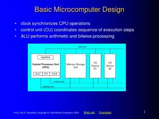
The PC’s Real-Time Clock An introduction to the capabilities and programming of the Real-Time Clock and CMOS memory
Non-Volatile Memory • The original IBM-PC had no internal clock • Users had to run a utility program to reset the date and time after any system reboot • This defect was eliminated in the IBM-AT • A special battery-powered peripheral was added to keep track of the time and date • It also provided a small amount of memory which could retain configuration settings
Motorola’s MC146818A • PC-AT’s Real-Time Clock plus RAM was manufactured by Motorola Corporation • Other companies have ‘cloned’ this chip • Its capabilities are described online in an official datasheet by Dallas Semiconductor (see ‘Maxim’ integrated circuit: DS12887) • You can also get the Motorola datasheet (by writing to its corporate headquarters)
Features of DS12887 • Can operate over ten years without power • Counts seconds, minutes, hours, days, day-of-the-week, date, month, and year (with leap-year compensation), valid up until the year 2100 AD, with options for 12/24-hour clock and Daylight Savings • Can use binary or BCD representation • Provides 114 bytes of nonvolative storage
Programming Interface • The RTC interfaces with system software as an array of 128 bytes, accessed via i/o ports 0x70 and 0x71 using a multiplexing scheme: port 0x70: address-port port 0x71: data-port • A system quirk: The most significant bit at port 0x70 is used to control a gate that can ‘mask’ the Non-Maskable Interrupt circuitry
Ten clock/calendar bytes Current seconds 0x0 0x1 0x2 0x3 0x4 0x5 0x6 0x7 0x8 0x9 Range is 0..59 Range is 0..59 Range is 0..59 Range is 0..59 Range is 0..23 or 1..12 Range is 0..23 or 1..12 Range is 1..7 (Sunday=1) Range is 1..31 Range is 1..12 (January=1) Range is 0..99 Alarm seconds Current minutes Alarm minutes Current hours Alarm hours Day-of-the-Week Date of the Month Current Month Current Year
Operating Capabilities • The RTC can be programmed to generate an interrupt under any combination of the following three conditions: 1) time/date counters were updated 2) current time equals the alarm time 3) periodic frequency interval restarts • The frequency of the periodic interrupt is a selectable rate (e.g., from 122 to 500ms)
Four Status/Control bytes UIP Divider bits Rate-Select 0xA 0xB 0xC 0xD SET PIE AIE UIE SQWE DM 24/12 DSE IRQF PF AF UF 0 0 0 0 VRT 0 0 0 0 0 0 0
Other NVRAM locations • Besides these 14 dedicated RTC bytes, there are 114 byte locations which can serve as nonvolatile storage in whatever manner the system designer decides • IBM has established some ‘standard’ uses for many (but not all) of these locations • A fairly complete CMOS Memory Map is accessible online (see course website)
Example: Diagnostic Status Power Status failure Check Sum bad POST Config invalid RAM Size wrong Fixed Disk bad CMOS Time invalid reserved reserved 0xE During the Power-On Self-Test, the ROM-BIOS routines perform tests of the memory and peripheral devices, and record any failures/errors in this Diagnostic Status byte
Note on the NMI circuitry • The CPU has a special input-signal that is ‘non-maskable’ (i.e., CLI / STI instructions have no effect on it), intended to be used for signaling urgent or catastrophic events (such as loss of power or memory failures) • But sometimes, during a “critical section” of system code, it is necessary to prohibit even these urgent interrupts (e.g., when stack or Interrupt Descriptors are invalid)
Non-Maskable Interrupt gate CPU Error-signals AND NMI Logic GATE (port 0x70, bit 7) PIC PIC IF INTR IRQ 0-7 IRQ 8-15
Example: setting alarm time ; inhibit clock updates while reprogramming mov $0x8B, %al # access register B out %al, $0x70 # and disable NMI in $0x71, %al # read register B or $0x80, %al # set the SET bit out %al, $0x71 # write register B
Set the alarm for 6:30:00 am mov $0x0685, %ax # hours out %ax, $0x70 mov $0x3083, %ax # minutes out %ax, $0x70 mov $0x0081, %ax # secons out %ax, $0x70
Finish SET (and reenable NMI) # clear the ‘SET’ bit in register B mov $0x8B, %al # select register B out %al, $0x70 # for access w/o NMI in $0x71, %al # read register B and $0x7F, %al # clear its SET bit out %al, $0x71 # write register B # reenable the Non-Maskable Interrupts mov $0x0D, %al # select register D out %ax, $0x70 # and reenable NMI
Our ‘rtcdemo.s’ program • We illustrate the Real-Time Clock chip’s ‘update’ interrupt by redisplaying the time whenever the clock-counters are updated • Register B controls which interrupts occur • But don’t change bits 0, 1, 2 (they control the data-format (binary or BCD), select 12 or 24 hour clock, and activate the Daylight Savings Time counter-compensation
Event-Queue paradigm HEAD free free Event record Event record Event record free free free base edge TAIL The Interrupt Service Routine(s) insert new event-records in the queue, while the main application-loop removes event-records from the queue.
An important ‘design pattern’ • Many modern user-centered applications use the ‘event-queue’ paradigm: initialize_the_system(); while ( !done ) { dequeue_next_event( &event_record); process_that_event( &event_record ); } cleanup_the_system(); exit(0);
In-class exercise • Modify our ‘rtcdemo.s’ program so that an ‘alarm’ interrupt will get triggered after an agreed amount of time has elapsed (for example, 10 seconds) and use that event to exit the program’s main loop (instead of using the built-in loop-counter variable)
Suggested implementation • Easiest and most elegant way to achieve the requested program modification is to adjust the Interrupt-Service Routine so it will save a 4-part event-record (instead of a 3-part event-record), the new item to be included is the RTC status-register value • Then the main loop can test the status it finds within an event-record, and can either loop or exit, depending on which event-type it found