Download
1 / 60
610 likes | 762 Views
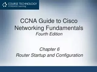
Design of the MultiService Router (MSR): A Platform for Networking Research. Fred Kuhns Washington University Applied Research Laboratory. http://www.arl.wustl.edu/arl/project/msr. Presentation Overview. Overview: Motivation, Context and Requirements System Architecture

E N D
Design of the MultiService Router (MSR): A Platform for Networking Research Fred Kuhns Washington University Applied Research Laboratory http://www.arl.wustl.edu/arl/project/msr
Presentation Overview • Overview: • Motivation, Context and Requirements • System Architecture • IP Forwarding in the MSR • Introduction to the Control Protocol
get app. spec.& plugin code determine best config. add destination host codeservers open_session(type,args) Session Establishment Motivating Example • Gigabit links • Traffic isolation • Security and DOS • Rapid prototyping • Experimental protocols • Resource reservations and guarantees • Embedded applications and active processing
Hosts LAN B Hosts LAN A Net G Port 1 Port 2 CR AR Net C Net D Port 2 Port 1 Net B AR Net E Net A CR Net F Identifying Design Requirements • MSR must support Ethernet or ATM using PVCs • Multiple hosts/routers per physical interface • One or more routers a network/LAN
MSR Project Goals • Develop an open, high performance and dynamically configurable Multiservice routing platform for use in Networking Research: • Support gigabit link speeds • independent of specific link technologies • Port Processor independence: SPC, FPX or Both • Configuration discovery at initialization time • Optimized packet processing in hardware (FPX) • IP forwarding and advanced packet scheduling • Active processing in hardware (FPX) • Support prototyping of new functions in software (SPC) before migrating to the FPX
MSR Project Goals • Create framework for experimenting with new protocols for traditional routing or resource management (QoS). • Extensible and robust software frameworks • Router control and resource management • Support conventional routing protocols such as OSPF • Avoid needless abstractions • Leverage existing and legacy efforts • Leverage existing code or libraries • Gigabit kits program, Extreme Networking project and Programmable Networks vision
Three Core Areas • Hardware architecture and performance • High-performance forwarding path and core interconnect • Hardware Components: • WUGS, APIC, SPC and FPX provide core components • Top-Level Functional Requirements (Framework) • Captures the management and control operations. In the MSR, most top-level functions are implemented on a centralized control processor. • Port-level Functional Requirements (Framework) • The IP forwarding path, active processing and port level control functions. Also statistics and monitoring.
Top-Level Framework • System Initialization: default routes and resources • Routing and Signaling • Extensible framework for routing protocol support (zebra). • Active routing: extended version of OSPF (Ralph Keller) • Associating received LSA with correct MSR interface • Forwarding table management/distribution (SPC and FPX) • Local Management and Control • Configuration discovery and initialization • Monitor and control local resources • Resource reservations: admission control, allocation and policing • API for plugin loading/unloading, instance creation/instance deletion, binding instances to filters, filter creation/deletion
Port-Level Functional Requirements • Control and management interface • Per flow or flow aggregate Resource allocation • Packet classification and general filters • Distributed Queuing (DQ) • Fair queuing at output ports (DRR) • Flow based resource allocations • IP Forwarding • Standard IP best-effort forwarding • Reserved flow forwarding - exact match • Active Processing Support • Plugin environment • Monitor and control resource usage • Dynamic plugin download and execution
Status: Complete • Initial architectural design and implementation complete: • software modules and hardware components • Core software module design and implementation complete: general filter, exact match classifier, fipl, distributed queuing, active processing, virtual interfaces, port command protocol. • Testing of IP forwarding function in FPX complete. • Initial DQ testing complete • Queue State DRR simulation and initial integration complete.
Status: Current Effort • Analysis and Enhancement of the • Distributed Queuing algorithm and its implementation. • exact match classifier and route pinning with reservations • Validate DRR • Test and verify Wave Video plugin and demo • Simple flow entry and route cache timeouts • Validate plugin bindings to exact match classifier • Routing protocol support (OSPF and Zebra)
Services Planned for Development • Extreme Networking - http://www.arl.wustl.edu/arl/projects/extreme: • Lightweight Flow Setup Service • one-way unicast flow with reserved bandwidth, soft-state • stable rate and transient rate reservations • Network Access Service (NAS) • provides controlled access to LFS • registration/authentication of hosts, users • resource usage data collection for monitoring, accounting • Reserved Tree Service (RTS) • configured, semi-private network infrastructure • reserved bandwidth, separate queues • paced upstream forwarding with source-based queues
Future Extensions to Basic MSR • Per source aggregate queues based on source prefix • DRR service; Discard policy is longest queue with hysteresis, discard front • Super scalable packet scheduling • approximate radix sort w/compensation (timing wheels) • Lightweight flow setup protocol implementation • flow identification in SPC, returns virtual output queue • framework for managing BW allocations and unfulfilled requests • interface to NAS • Reserved Tree Service: Hardware only. • Enhanced (per flow?) Distributed Queuing • NAS implementations: • User authentication, policy enforcement, monitoring & feedback
Presentation Overview • Overview of Project and status • System Architecture • IP Forwarding in the MSR • Control Path • SPC kernel processing • Control Protocol
MSR Hardware Components ControlProcessor Switch Fabric ATM Switch Core PP PP PP PP PP PP Port Processors LC LC LC LC LC LC Line Cards
Port Processors: SPC and/or FPX ControlProcessor Switch Fabric ATM Switch Core IPP OPP IPP OPP IPP OPP IPP OPP IPP OPP IPP OPP FPX FPX FPX FPX FPX FPX Port Processors SPC SPC SPC SPC SPC SPC LC LC LC LC LC LC Line Cards
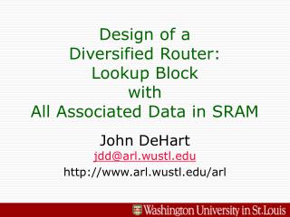
Example SPC and FPX Design Shim contains results of classification step SPC FPX DQ Module Z.2 Active Processing IP Classifier X.1 shim NID APIC Flow Control
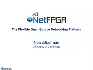
flexsig RSVP NCMO/Jammer OSPF classify classify MultiService Router - Overview CP - Control Processor RA - Route Agents MM – MSR Manager PP - Port Processor (SPC/FPX) PE – Processing Environment DQ – Distributed Queuing DRR – Deficit Round Robin FP – Forwarding Path Signaling Agents MSR CP MM RA framework Configure Routing OSPF NOC Signaling flexroutd Resource Net Manager App and GUI GBNSC (switch & ports) Local Interface PP PP PP PE MSR control PE plugin plugin plugin plugin WUGS DQ DQ classify/lookup classify/lookup FP DRR DRR FP PP PP PP PP PP
Top-Level Components • MultiService Router (MSR) • Control Processor (CP): System monitoring and control: • MSR Manager (MM): router configuration; signaling protocol; Forwarding db and Classifier rule set management; system monitoring; port level resource management and control; local admission control; discovers hardware configuration at startup . • Routing Agent (RA): local instance of routing protocols, communicates with remote entities. Sends route updates to RM. Currently Zebra based. • WUGS switch controller (GBNSC), used for monitoring functions: sends control cells to WUGS to read statistics and configuration information. • Port Processor (PP): Port level resource management. • Forwarding Path (FP): modules/components performing the core IP forwarding and port level control operations. Route lookup, flow classification, filtering, distributed queuing and fair output queuing. • Processing Environment (PE): infrastructure supporting active processing of IP datagrams. Application flows are bound to a software (or hardware module in the FPX) processing module.
Top-Level Components • Network Operations Center (NOC) - GUI interface • Network Management Application • Active metric collection • Passive monitoring of DQ. Display formats include format, temporal resolution, processing overhead. • Metric and display evaluation • Active management not implemented. • Supports MSR Testing • test/demo configuration and setup • identify meaningful metrics and display architecture • Display and "manage" MSR configuration • interface to init MSR, change per port attributes • reset MSR • set runtime parameters
MSR Manager Operational Control Policy Manager GBNSC Config Resource Manager IP Routing Manager flexsig MSR Abstraction Layer Configuration Switch & APIC Control/Cell Libs FPX Control Logic/Cell Libs SPC Libs Cmd/Msg MSR Wrappers Native ATM Library "raw" Native ATM UDP TCP INET API IP Device (APIC) Driver (Common Code) The Control Processor
Control Processor Tasks • The Top-Level framework, Currently supports: • MSR Initialization • Data collection for the Management tool • Test and Demo Environment Support • Routing support - in development. • OSPF - Standard Routing Protocols • Local resource management and global signaling • Monitor resource usage • Support Active Processing - plugins
Requirements - RM • Resource identification and initialization: • Create and distribute routing tables to port processors • constructed using OSPF and a QoS routing protocol • Distributed queuing (DQ) management • reserves output link BW and sets policies. • Allocation of resources within individual ports • Static allocation - configuration script or admin commands • Dynamic allocation or re-allocation • out-of-band allocation by manager • out-of-band allocation by signaling agents • in-band as needed by particular services
Port 1 Port 2 Port 3 Port N Distributed Routing Table Admin VC space and BW - Admission Cntrl OSPF RSVP OSPF# ... route tables EN flow table IP Resource Management Merge Tables ...
Routing Support • Context: Programmable Networks • Focus: Software Component Architecture • Issues: • Building, maintaining and distributing route tables • Delivery of updates (LSAs from neighbors) to CP • Format of route table entries • Support for logical interfaces (sub-interfaces) • CP component interactions (APIs): • Routing - Zebra, OSPFd and msr_route_manager • signaling and resource manager • Assumptions: • All routing neighbors are directly attached
Presentation Overview • Overview of Project and status • System Architecture • IP Forwarding in the MSR • Control Path • SPC kernel processing • Control Protocol
MSR 0.5 – Basic IP Forwarding • Core functions implemented in basic MSR system (aka Version 0.5) • Control Processor • System monitoring • System configuration • Port level Software (SPC): • Fast IP Lookup (FIPL) and Table management • APIC Driver (the engine) • MSR Memory management (buffers) • High priority periodic callback mechanism • Distributed Queuing • General Classifier and an active processing environment
Phase 0.5 - Basic IP Forwarding CP One connected IP entity per port Control Traffic SPC/FPX SPC/FPX IP router router IP SPC/FPX SPC/FPX IP router router loopback IP WUGS Does not show distributed queuing
Distributed Queuing • Goals • Maintain High Output Link Utilization • Avoid Switch Congestion • Avoid Output Queue Underflow • Mechanisms • Virtual Output Queuing (VOQ) at the inputs • Broadcast VOQ and output backlogs every D sec • Each PPi recalculates ratei,j every D sec
DQ - Cell Format • Broadcast DQ summary cells every D sec: • Src port - sending port number (0-7) • Overall Rate - total aggregate rate (BW) allocated to this port for the port-to-switch connection –currently not used • Output queue length - bytes queued in output port’s output queue. • VOQ X Queue Length - number of bytes queued in src port’s VOQ for output port X. VCI = DQVC 32 0 Cell Header Src port Overall Rate Output Queue Length Padding VOQ 0 Queue Length VOQ 1 Queue Length VOQ 2 Queue Length VOQ 3 Queue Length VOQ 4 Queue Length VOQ 5 Queue Length VOQ 6 Queue Length VOQ 7 Queue Length
MSR Router: Distributed Queuing out Qs out Qs out Qs out Qs out Qs out Qs out Qs out Qs out Qs out Qs out Qs out Qs out Qs out Qs out Qs out Qs Read all summary cells (including own) and calculate output rate for each VOQ. DQ summary cells wait in queue for start of next cycle Determine per output port queue depth Create DQ summary cell for this port and Broadcast cell to all input ports (including self) DQ updates packet scheduler to pace each VOQ according to backlog share p0 p8 p8 p0 ... ... queue queue p0 p8 p8 p0 ... ... queue queue p0 p8 p8 p0 ... ... queue queue p8 p8 p8 p8 p8 p8 p8 p8 p0 p0 p0 p0 p0 p0 p0 p0 ... ... ... ... ... ... ... ... p0 p0 p0 p0 p0 p0 p0 p0 p8 p8 p8 p8 p8 p8 p8 p8 queue queue queue queue queue queue queue queue ... ... ... ... ... ... ... ... queue queue queue queue queue queue queue queue p0 p8 p8 p0 ... ... queue queue cell hdr cell hdr cell hdr cell hdr cell hdr cell hdr cell hdr cell hdr cell hdr cell hdr cell hdr cell hdr cell hdr cell hdr cell hdr cell hdr cell hdr cell hdr cell hdr cell hdr cell hdr cell hdr cell hdr cell hdr cell hdr cell hdr cell hdr cell hdr cell hdr cell hdr cell hdr cell hdr cell hdr cell hdr cell hdr cell hdr cell hdr cell hdr cell hdr cell hdr cell hdr cell hdr cell hdr cell hdr cell hdr cell hdr cell hdr cell hdr cell hdr cell hdr cell hdr cell hdr cell hdr cell hdr cell hdr cell hdr cell hdr cell hdr cell hdr cell hdr cell hdr cell hdr cell hdr cell hdr cell hdr cell hdr cell hdr cell hdr cell hdr cell hdr cell hdr cell hdr DQ data DQ data DQ data DQ data DQ data DQ data DQ data DQ data DQ data DQ data DQ data DQ data DQ data DQ data DQ data DQ data DQ data DQ data DQ data DQ data DQ data DQ data DQ data DQ data DQ data DQ data DQ data DQ data DQ data DQ data DQ data DQ data DQ data DQ data DQ data DQ data DQ data DQ data DQ data DQ data DQ data DQ data DQ data DQ data DQ data DQ data DQ data DQ data DQ data DQ data DQ data DQ data DQ data DQ data DQ data DQ data DQ data DQ data DQ data DQ data DQ data DQ data DQ data DQ data DQ data DQ data DQ data DQ data DQ data DQ data DQ data DQ data wugs 192.168.200.X 192.168.204.X P4 P0 SPC/FPX SPC/FPX Next/Prev Hop Next/Prev Hop DQ DQ 192.168.205.X 192.168.201.X P5 P1 SPC/FPX SPC/FPX Next/Prev Hop Next/Prev Hop DQ DQ At each port, DQ runs every D sec 192.168.202.X 192.168.206.X P6 P2 SPC/FPX SPC/FPX Next/Prev Hop Next/Prev Hop DQ DQ 192.168.202.2 192.168.203.X 192.168.207.X P7 P3 SPC/FPX SPC/FPX Next/Prev Hop CP DQ DQ 192.168.203.2
Distributed Queuing Algorithm • Goal: avoid switch congestion and output queue underflow. • Let hi(i,j) be input i’s share of input-side backlog to output j. • can avoid switch congestion by sending from input i to output j at rate LShi(i,j) • where L is external link rate and S is switch speedup • Let lo(i,j)be input i’s share of total backlog for output j. • can avoid underflow of queue at output j by sending from input i to output j at rate Llo(i,j) • this works if L(lo(i,1)+···+lo(i,n)) LS for all i • Let wt(i,j) be the ratio of lo(i,j) to lo(i,1)+···+lo(i,n). • Let rate(i,j)=LSlo(wt(i,j),hi(i,j)). • Note: algorithm avoids congestion and avoids underflow for large enough S. • what is the smallest value of S for which underflow cannot occur?
MSR IP Data Path - An Example WUGS 192.168.204.X 192.168.200.X P4 P0 SPC/FPX SPC/FPX CP Next/Prev Hop IP fwd DQ DQ 192.168.200.2 192.168.204.2 192.168.205.X 192.168.201.X P5 P1 SPC/FPX SPC/FPX Next/Prev Hop Next/Prev Hop DQ DQ 192.168.206.X 192.168.202.X P6 P2 SPC/FPX SPC/FPX Next/Prev Hop Next/Prev Hop DQ DQ 192.168.202.2 192.168.203.X 192.168.207.X P7 P3 SPC/FPX SPC/FPX Next/Prev Hop Next/Prev Hop IP fwd DQ DQ 192.168.203.2
MSR Version 1.0 - Enhanced • Control Processor • Configuration discovery • enhanced download with broadcast • Command protocol implementation • Port level Software (SPC): • Virtual Interface support and Shim processing • Dynamic update of FIPL table • MSR Memory Management enhancements • Distributed Queuing • Exact Match Classifier • Command protocol implementation • Embedded Debug facility
CP Virtual Interfaces on ATM No PVC, No Traffic to/from MSR R R Port 1 SPC/FPX 2xx ATM Switch Port 3 X Port 0 Port 2 43 50 VC=50 44 lookup 42 51 Port 1 Port 3 40 40 VC=51 50 43 out out 42 Host 51 44 Port 4 Port 2
RM RA config ospf IP (udp/tcp) 50 51 53 Internal MSR Connections (SPC only) CP Sockets: Communication endpoints ... IP layer: routes pkts to/from sockets socket atm VP0 VP1 VP2 VP3 Driver: routes pkts between interface and net layer raw atm 50 51 52 53 Virtual Interfaces, or Virtual Ports (VP) Port 0 SPC • Port loopback not shown • IP Address bound to virtual interfaces • only ip fwd path shown lookup/out processing SPC SPC Port 3 Port 1 63 63 control control 41 43 50 42 44 51 44 out out lookup 42 52 52 40 40 53 40 40 50 50 41 43 51 51 out out 42 42 lookup 52 52 44 44 53 53 SPC SPC Port 2 63 63 Port 4 control control 43 41 50 50 41 43 51 51 42 out out 44 lookup 52 52 40 40 53 53 40 40 50 50 43 41 51 51 WUGS 41 out out 43 lookup 52 52 44 42 53 53
plugins plugins FIPL FIPL IP proc IP proc Packet Routing, SPC and FPX Ingress Egress • IP eval: IP processing for FPX. • Broadcast and Multicast destination address • IP options • Packet not recognized WUGS Current VCI Support: 1) 64 Ports (PN) 2) 16 sub-ports (SP) SPC SPC Ether only VC from endstations Ether only VC to endstations shim demux shim update shim update shim demux FPX FPX 63 63 Link Interface Link Interface add shim shim proc. rem shim FIPL ... ... 64 ... 127 64 ... 127 (out port + 64) (in port + 64) From previous hop router Inbound VC = SPI + 128 0 <= SPI <= 15 Currently Support at most 4 Inbound VCs: One for Ethernet or Four for ATM VCs to next hop routers (p2p conn) Outbound VC = SPI + 128 0 <= SPI<= 15
CP VP0 shim shim shim shim Using Virtual Interfaces 50 Port 0 SPC/FPX shim processing Port 1 Port 3 SPC/FPX SPC/FPX 41 43 50 50 42 44 • Input port • lookup IP route • Insert shim • send to output 44 lookup 42 51 51 40 40 40 40 50 50 41 43 out 42 42 lookup 51 51 44 44 Port 2 Port 4 SPC/FPX SPC/FPX • Output port • Reassemble frame • get out VIN from shim • remove shim • send to next hop/host 43 41 50 41 50 43 51 42 lookup 44 52 40 40 40 40 50 43 41 51 50 WUGS 41 43 lookup 52 44 42
src: 192.168.220.5 dst: 192.168.200.1 sport: 5050 dport: 89 50 51 52 53 data Packet Forwarding Port:0 SubPorts: 0-3 VIN 0: 192.168.200.1/24:Ext. Link VC 50 VIN 1:192.168.201.1/24:Ext. Link VC 51 VIN 2:192.168.202.1/24:Ext. Link VC 52 VIN 3:192.168.203.1/24:Ext. Link VC 53 CP RM RA Configure zebra Resource OSPF Signaling Routing flexroutd Port:5 SubPorts: 0-3 VIN 20: 192.168.220.1/24:Ext. Link VC 50 VIN 21:192.168.221.1/24:Ext. Link VC 51 VIN 22:192.168.222.1/24:Ext. Link VC 52 VIN 23:192.168.223.1/24:Ext. Link VC 53 Discover (switch & ports) interfaces PP P0 PP PP IP packet P5 P1 WUGS P2 P3 P6 P4 P7
shim src: 192.168.220.5 dst: 192.168.200.1 sport: 5050 dport: 89 50 51 52 53 data Forwarding IP Traffic • Driver reads header and performs route lookup, returns fwd_key: • fwd_key = {Stream ID, Out VIN} • SID = reserved session ID, local only • VIN = {Port (10 bits), SubPort (6 bits)} • Insert shim, update AAL5 trailer and IP header. • calculate internal VC from output VIN’s port number (VC = 40) CP RM RA Configure zebra Resource OSPF Signaling Routing flexroutd Discover (switch & ports) interfaces PP lookup/out P0 PP PP P5 P1 ip lookup WUGS P2 192.168.200.1 -> fwd_key P3 P6 Lookup destination in table: 192.168.200.1/24 matches - Out VIN 0 P4 P7
Internal IP Packet Format 8 Bytes Shim Version H-length TOS Total length Identification Flags Fragment offset TTL Protocol Header checksum IP Header Source Address Destination Address IP Datagram IP Options ?? IP data (transport header and transport data) AAL5 padding (0 - 40 bytes) AAL5 Trailer CPCS-UU (0) CPCS-UU (0) Length (IP packet + LLC/SNAP) CRC (APIC calculates and sets)
PN (10 bits) SPI (6 bits) IntraPort Shim: Field Definitions 31 15 0 Stream Identifier Not Used Flags Input VIN Output VIN Flags Virtual Interface Number Format X AF NR OP UK • Flags- Used by SPC to demultiplex incoming packets.The FPX sets flags to indicate reason for sending packet to SPC. Note, may also use flags to implement flow control. • AF: Active Flow. • NR: No route in table. • OP: IP Options present (Correct version but incorrect header size). • UK: Unknown packet type (incorrect version for example). • Stream Identifier (SID):Identifier for reserved traffic, locally unique label. • FPX fills in for reserved flows. • Input VIN- The physical port and sub-port packet arrived on. PN is the physical port number and SPI is the sub-port identifier. There is a set map from SPI to VCI. • FPX sets these values. Not clear that we need this in the IntraPort shim. • VCI = Base VC + SPI • Output VIN - output port and sub-port. • The FPX sets this if the route lookup succeeds. • If the SPC performs the lookup for the FPX then the SPC fills in. • The SPC may also modify this value in order to re-route a packet - modifying seems dangerous, but setting ok.
PN (10 bits) SPI (6 bits) InterPort Shim: Field Definitions 31 15 0 Not Used Flags Input VIN Output VIN Flags Virtual Interface Number Format X • Used to convey forwarding information to output port. Currently only the Output SPI is necessary for forwarding. • Flags: TBD. • Input VIN – Same as IntraPort Shim. • Ingress FPX or SPC when FPX is not used. • Output VIN – Same as IntraPort Shim.
FPX version of FIPL table entry (36 bits): 35 31 16 15 0 Output VIN Stream Identifier A TBD SPC version of FIPL table entry (32 bits): 31 16 15 0 Output VIN Stream Identifier Virtual Interface Number Format 15 5 0 PN (10 bits) SPI (6 bits) FIPL Table Entry Formats
PP shim (to VIN 0) P0 PP src: 192.168.220.5 dst: 192.168.200.1 sport: 5050 dport: 89 src: 192.168.100.5 dst: 192.168.214.1 sport: 5050 dport: 89 PP P5 P1 50 51 P2 52 53 data data Forwarding IP Traffic • At Port 0, driver extract shim and determines the destination VIN • Output VIN converted to output VC = 50 • Removes shim, updates AAL5 trailer and sends on VC 50 (in this case the packets goes to the CP) CP RM RA Configure zebra Resource OSPF Signaling Routing flexroutd Discover (switch & ports) interfaces shim processing Route Advertisement WUGS P3 P6 P4 P7
PP P5 50 51 52 53 Example: Processing Route Updates • CP kernel delivers packet to socket layer • Packet read by OSPFd, • Senders IP address is mapped to interface ID • OSPFd and Zebra associate received advertisement with an MSR input VIN (VIN20 in this case). CP RM RA Configure zebra Resource OSPF Signaling Routing flexroutd socket Discover (switch & ports) Interfaces PP P0 PP P1 WUGS P2 P3 P6 P4 P7
PP P5 52 53 54 55 Note on Sockets, IP and Interfaces • What if packet arrives on interface with different address? • Do we care? • Example: Packet sent to CP but arrives at port 7 on different VP. • CP kernel will still send pkt to socket bound to 192.168.200.1 • If all neighbor routers are directly attached, then it doesn't matter. We can distinguish by looking at sending IP address. CP RM RA Configure zebra Resource OSPF Signaling Routing flexroutd socket Discover (switch & ports) Interfaces PP P0 PP P1 src: 192.168.100.5 dst: 192.168.205.1 sport: 5050 dport: 89 WUGS P2 P3 P6 data P4 P7
PP P5 52 53 54 55 Example: Processing Route Updates • OSPFd notifies zebra of any route updates. • Zebra provides a common framework for interacting with system • Zebra passes route updates to he MSR Route Manager CP RM RA Configure zebra Resource OSPF Signaling Routing flexroutd Discover (switch & ports) Virtual Interfaces PP P0 PP P1 WUGS P2 P3 P6 P4 P7
Route Distribution and Port Updates CP RM RA Add destination vector and output port/VC Configure zebra Resource OSPF Signaling Routing flexroutd Discover (switch & ports) "Broadcast" update Virtual Interfaces PP P0 PP PP 192.168.205.1 WUGS PP PP PP PP PP
Presentation Overview • Overview of Project and status • System Architecture • IP Forwarding in the MSR • Command Protocol and Debugging Messages • sendcmd() and the CP to PP Control Path