Download
1 / 28
280 likes | 411 Views
Team BAKE presents the design and implementation of a wireless autonomous vehicle equipped with a camera and paintball gun. This project encompasses mechanical design, logic circuits, motor drivers, and memory mapping. The vehicle features motion, video, audio, and light sensors, controlled via 802.11B communication. Real-time data transmission is achieved to enable user interaction. The system utilizes a stepper motor and a system of gears to operate the paintball gun. With milestones set for functionality testing and complex operations, this vehicle aims to demonstrate innovative engineering solutions.

E N D
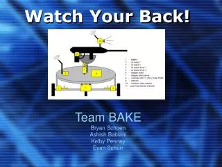
Watch Your Back! Team BAKE Bryan Schoen Ashish Bablani Kelby Penney Evan Schurr
Overview of Presentation • Description of Mechanical Design 2. Description of Logic Circuit + Progress 3.Description of Motor,Drivers 4. Memory map, CPLD, Stepper 5. Milestone Targets & Work Distribution
Description • Wireless autonomous vehicle equipped with a camera and paintball gun • Sensors may include: motion, video, audio and light • Vehicle can be controlled by 802.11B communication • The data will be transferred back wirelessly to a computer with a controller (keyboard) • Data can be viewed and controlled in real time by a user interface
Gear System • Created in Solid Works via Gear Trax • 2 Spur Gears • Small gear will be attached to the shaft of the stepper motor and will displace the larger gear • Larger gear will have gun attached to it • Gear system will be • attached to the top of • this unit
Gears Gun Large Gear Small gear 1 of 2 Support Columns That Attach to the Platform Stepper Motor
Servo Motor Driver • LMD18200 • 3A H-Bridge motor • Bipolar circuitry • Accomodates peak output currents up to 6A • Delivers up to 3A continuous output • Operates at supply voltages up to 55V
PMI Piranha EFORCE EXT • 9V input power for electronic trigger • C02 powered • Various modes – single shot, burst, full auto • Trigger controlled by solenoid piston • PROBLEMS!!!
Processor – Motorola HC11K1 • 16 bit address • 8 bit data • 8 MHz clock • 4 PWM outputs for motor drivers • Memory map to the right • Uses accumulator A & B for data registers • Read and write data and address on falling edge of E clock (1 MHz)
Memory Mapping • Internal memory • $0 - $0FFF • Ram • $1000 - $7FFF • Flash • $8000 - $FFFF
CPLD Logic • Input Pins • Top 4 MSB address bits • Output Pins • Chip select to Ram when address bits are $1 - $7 • Chip select to Flash when address bits are $8 - $F • Future chip select to DC servo motor drivers and Stepper motor driver • Add 2 more address bits
A3967 Stepper Motor Driver • Controlled by PWM output of microcontroller • Can microstep up to 1/8 of 1.8 degrees • Output current limit – 750 mA • Sleep function to minimize power loss • Thermal shutdown temperature of 165 degrees C
Wireless Web Cam & Router The WebCam -Plug and play -Great Resolution (640*480) -Control of Movement -Remote Management The Router -helps communicate between PC & WebCam -helps in sending control signals to the WebCam
RS232 connection Max233A -Driver for the rs232 interface -Dual transceiver and has internal capacitors (saves space on board) The Adapter -One end (DB9) connects to a PC or any other terminal. -The other end provides a 4-pin header to connect to any micro controller board that requires serial I/O
Final Parts • The Brain • Clock – 8MHZ • Data and address buffers - • Microprocessor – Motorola MC68HC11K1 • CPLD – 44PIN -XC9572 • Flash RAM • Rom - EEPROM • Test Pins • Power Strips • RS232 ports - MAX233A
Final Parts • The Motor • Servo Driver Chips , National Instruments • Stepper Driver Chips, Allegro A3967 • Servo Motors, DC servo disc motors • Stepper Motor , Sure-Step • Power Strips
Final Parts • The Others • Base Platform • Plastic Gear • “Air powered launcher” • Wireless Web Cam • Wireless Router • Solenoid • *RF transmitter (HAC-UM) • **Sensors
Hardware Implementation 44 pin CPLD Wireless Web-Cam Control signal Serial RS-232 Motorola 68HC11K1 Micro-Processor Paintball gun - trigger Wireless transmission Driver for trigger Rom DC Motor Drivers Ram 1 Stepper Motor Computer 2 DC Servo Disc Motors Devices Built, incorporated & tested Currently in progress
Timeline Status • By Milestone 1 - We should have the following: • The servos motors – should be able to move as we expect it to, giving it the control signals from the computers keyboard it should move smoothly and in the appropriate direction. • The stepper motor – should also move up and down as required and also making sure that it also does this very smoothly (using the driver for this motor will allow us to take 1/8th of a single step 1.8Degrees / 8 = 0.225 Degrees / Step) • The RS232 – making sure that giving the instructions from the computer is interpreted as required • Connection between our brain circuit with the motor circuit – this will enable us to use the brain part of the circuit to control the functions of the motor drivers which then will control the movement of all the motors. • Testing everything for basic functionality
Timeline Status • By Milestone 2 - We should have the following: • More complex functions for our system – such as automated functions like the Valentines Day Massacre • Incorporate the RF device (HAC-UM) from SPARKFUN
Timeline Status By EXPO - We anticipate to have the following: Have complete desired functionality of our system including • Complex Logic • Wireless Control • Ability to sense objects (to avoid crashes) • Smooth operation of all our motors • Smooth operation of our overall system
Distribution of Work Kelby -Setting up the stepper motor and driver -Setting up the microprocessor + Ram + ROM + Buffers & CPLD Evan -Designing the Gear mechanism to hold the gun -setting up the Servo motors and drivers -Wireless Web-Cam setup + UI Bryan -Programming the CPLD -Setting up the microprocessor + Ram + ROM + Buffers & CPLD Ashish • Programming the microprocessor • Setting up the Servo Motors and drivers • RS232 Interface (between PC and board) + UI