Download
1 / 13
130 likes | 294 Views
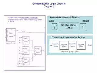
Lattice Diagrams using Reed-Muller Logic. 2002.10.15 Shim, Hee Jun. Introduction. To realize arbitrary Boolean functions in a regular and planar layout Universal Akers Array (UAA)

E N D
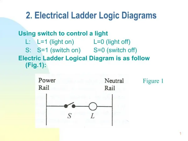
Lattice Diagrams using Reed-Muller Logic 2002.10.15 Shim, Hee Jun
Introduction • To realize arbitrary Boolean functions in a regular and planar layout • Universal Akers Array (UAA) • This paper presents an extension of UAAs, called “Lattice Diagrams” and the efficient method of mapping arbitrary multi-output functions.
Background • Lattice Diagram • Data structures that describe both regular geometry of connections and a logic of a circuit. • Expansion type • Shannon : F = a·Fa @ a’ ·Fa’ • Positive Davio (pD) : F = a(Fa@Fa’) @ 1·Fa’ • Negative Davio (nD) : F = 1·Fa @ a’(Fa@Fa’) • Array to explain Lattice concepts • Each block means a function.
Classification of Lattice Diagram • Order • Ordered ~ : one variable on a diagonal (=level) • Ordered ~ with Repeated Variables : one variable in a level, but the same variable may appear on various levels. • Free ~ : different orders of variables in the paths leading from leafs to the root • Folded ~ : Free ~, but the order of variables in levels must be the same, with some variables possibly missing. • Expansion • All expansions are of the same type. • Shannon ~ : Shannon • Functional ~ : pD. • Negative Functional ~ : nD. • All expansions in every level are of the same type. • Reed-Muller ~ : pD, nD. • Kronecker ~ : Shannon, pD, nD. • All expansions in every level are either of some expansion types. • Pseudo Reed-Muller ~ : pD, nD • Pseudo S/pD ~ : Shannon, pD • Pseudo S/nD ~ : Shannon, nD • Pseudo Kronecker ~ : Shannon, pD, nD
Background • Joining Rule • R= 1·x@b(by@b’z) = 1·x@by • S= 1·(by@b’z)@ b·(y@z@v) = (by@by)@ z(b’@b)@ bv = 0@(z·1)@bv = 1·z@bv
Method of Creating Lattice Diagram • Ordered Shannon Lattice Diagram (OSLD) • It is expanded level-by-level, starting from the root level, and from left to right in every level. • In contrast to standard BDDs, the joining operation combines also non-isomorphic nodes of trees. • Shannon Expansion: F = a·Fa @ a’ ·Fa’ • Joining Rule
Method of Creating Lattice Diagram Single-output OSLD Example 1
Method of Creating Lattice Diagram Example 2 Multi-output OSLD
Method of Creating Lattice Diagram Folded SLD Multi-output OSLD 1 2 1 2 a a’ a a’ a’ a a 3 4 3 4
Method of Creating Lattice Diagram • Functional Lattice Diagram • It is like for OSLD. • Positive Davio expansions are used instead of Shannon and the (pD,pD) joining rules instead of the (S,S) joining rules. • Positive Davio (pD) : F = 1·Fa’ @a(Fa’@Fa) • Joining Rule (pD, pD) : 1@ad@bd@abd a@b@d@bd d d 1 1 1 (1)@(1@a@b@ab) = a@b@ab a@b (a@b)@(a@1) = b@1 d(a@b@ab) @ d’(a@b) = a(d@d’)@b(d@d’)@abd = a@b@abd a@b@ab @ a@b @ b@1 =ab@b@1
Method of Creating Lattice Diagram • Folded Kronecker Lattice Diagram • The rectangular envelope area has been reduced. • Ordered Kronecker Lattice Diagrams (OKLD) • It uses the joining rules, (S,S), (pD,pD), (nD, nD) because all expansions in every level are of the same type.
Method of Creating Lattice Diagram • Pseudo-Kronecker Lattice Diagram • Pseudo S/pD Kronecker Lattice Diagram can be solved. ( only mixture of S and pD nodes in a level) • But, Joining rules cannot be created for combinations of expansion nodes (pD,nD) and (nD,S) • Open problem whether creating of Pseudo-Kronecker Lattice Diagrams for (S,pD,nD) can be solved analogously to the previous method.
Conclusion • Introduce method of creating various type of lattice diagram by combining together non-isomorphic nodes at the same level. • There is no constraint on repeating variables consecutively. • Use any subset of S, pD, and nD expansions. • Support arbitrary multi-output functions.