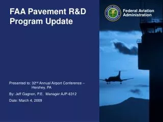
FAA Pavement Design
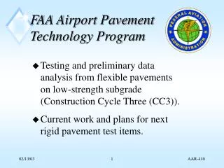
FAA Pavement Design. AC 150/5320-6E and FAARFIELD. 2008 Eastern Region Airport Conference. Rodney N. Joel, P.E. Civil Engineer / Airfield Pavement Airport Engineering Division. March, 2008. FAA Pavement Design. AC 150/5320-6E, Airport Pavement Design and Evaluation

FAA Pavement Design
E N D
Presentation Transcript
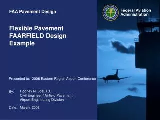
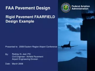
FAA Pavement Design AC 150/5320-6E and FAARFIELD 2008 Eastern Region Airport Conference Rodney N. Joel, P.E. Civil Engineer / Airfield PavementAirport Engineering Division March, 2008
FAA Pavement Design AC 150/5320-6E, Airport Pavement Design and Evaluation Note that this presentation will address significant changes to FAA pavement design procedures and is not intended to convey a complete overview of the pavement design procedure
FAA Pavement Design AC 150/5320-6E, Airport Pavement Design and Evaluation • Completely revised in 2008 • New design methodologies for Rigid and Flexible pavements • Software dependent design procedures • Addresses modern airplane parameters
Chapter 2 Soil Investigations and Evaluation • Very few significant changes • Still uses Unified Soil Classification (USC) system • Reference to ASTM 2487 GW CL GP ML GM OL GC CH SW MH SP OH SM PT SC
Chapter 2 Soil Investigations and Evaluation Same minimum subsurface boring recommendations Same soil testing recommendations
Chapter 2 Soil Investigations and Evaluation Continues to split soil compaction requirements based upon 60,000 lb gross weight airplane < 60,000 ASTM D 698 Standard Proctor > 60,000 ASTM D 1557 Modified Proctor
Chapter 2 Soil Investigations and Evaluation Soil Strength Parameter for FLEXIBLE pavement Subgrade Modulus (E psi) or CBR CBR • Design value – One Standard Deviation below the Mean • Lowest practical value CBR = 3 Otherwise stabilize or replace
Chapter 2 Soil Investigations and Evaluation Soil Strength Parameter for RIGID pavement Resilient Modulus E (psi) or Modulus of Subgrade Reaction – k-value (pci) • Design value – “conservative selection” • K-value can be estimated from CBR (k in pci)
Chapter 2 Soil Investigations and Evaluation Seasonal Frost • Same Frost Groups (FG-1, FG-2, FG-3 & FG-4) • Determination of Depth of Frost Penetration • Based on local Engineering experience • i.e. local construction practice, building codes, etc. • No nomographs or programs provided
Chapter 3 - Pavement Design • Completely New Chapter • Covers standard pavement design procedures for both flexible and rigid pavement • Applies to pavement designed for airplanes with gross weights exceeding 30,000 lbs • Design procedure requires the use of computer program, i.e. FAARFIELD
Chapter 3 - Pavement Design • Flexible Pavement Design based on Layered Elastic design procedure • US Corp of Engineers CBR Method no longer used • Rigid Pavement Design based on 3-Dimensional Finite Element model • Westergaard design procedure no longer used.
Chapter 3 - Pavement Design Traffic Models • New procedures require that ALL anticipated traffic be included in the traffic model. • Concept of “design aircraft” is no longer used • Cumulative Damage Factor (CDF) replaces need for design aircraft procedure.
Chapter 3 - Pavement Design Traffic Model - Cumulative Damage Factor • Sums Damage From Each Aircraft • Based upon its unique pavement loading characteristics and • Location of the main gear from centerline • DOES NOT use the “design aircraft” method of condensing all aircraft into one design model
Chapter 3 - Pavement Design Traffic Model - Cumulative Damage Factor • Sums Damage From Each Aircraft - Not From “Design Aircraft” • When CDF = 1, Design Life is Exhausted
Chapter 3 - Pavement Design Traffic Model - Cumulative Damage Factor • CDF is Calculated for each 10 inch wide strip over a total 820 inch width. • Gear location and wander considered for each aircraft • Use Miner’s rule to sum damage for each strip • Must Input Traffic Mix, NOT “Design Aircraft”
Chapter 3 - Pavement Design Traffic Model - Cumulative Damage Factor 10 inch Critical location Maximum Damage in any 10 inches A + B + C Runway Centerline CDF
Sample Aircraft Traffic Mix CDF Contribution Condition specific and not a general representation of noted aircraft
Sample Aircraft Traffic Mix CDF Contribution Condition specific and not a general representation of noted aircraft
Chapter 3 - Pavement Design Remember Must use the entire traffic mixture No more “Design Aircraft” Comparisons between new and previous design procedures using “design aircraft” for the traffic model will result in significant differences =
Chapter 3 - Pavement Design Traffic Model – Airplane Characteristics • FAARFIELD program currently provides 198 different aircraft models • Each model is unique with respect to gross load, load distribution, wheel spacing, and tire pressure • Gear types identified in accordance with FAA Order 5300.7 • Eliminates “widebody” terminology
Chapter 3 - Pavement Design Traffic Model – Gear Naming Convention Main Gear Designation Body/Belly Gear Designation # X # / # X # # of gear types in tandem Total # of body/belly gears (Because body/belly gear may not be symmetrical, the gear must identify the total number of gears present and a value of 1 is not omitted if only one gear exists.) (A value of 1 is omitted for simplicity.) Gear type, e.g. S, D, T, or Q # of main gears in line on one side of the aircraft Gear type, e.g. S, D, T, or Q (Assumes gear is present on both sides. The value indicates number of gears on one side. A value of 1 is omitted for simplicity.) # of gear types in tandem (A value of 1 is omitted for simplicity.)
Chapter 3 - Pavement Design Traffic Model – Gear Naming Convention Single S Dual D Triple T Quadruple Q
Chapter 3 - Pavement Design Traffic Model – Gear Naming Convention Single S Dual D Triple T Quadruple Q 2 Singles in Tandem 2S 2 Duals in Tandem 2D 2 Triples in Tandem 2T 2 Quadruples in Tandem 2Q 3 Singles in Tandem 3S 3 Triples in Tandem 3T 3 Duals in Tandem 3D 3 Quadruples in Tandem 3Q
Chapter 3 - Pavement Design -- Examples SSingle Wheel DDual Wheel 2DDual Tandem 3DB777 2D/D1DC-10 2D/2D1A340-600
Chapter 3 - Pavement Design -- Examples 2D/3D2A380 2D/2D2B747 C5Lockheed C5
Chapter 3 - Pavement Design Traffic Model – Pass to Coverage (P/C) Ratio • Lateral movement is known as airplane wander and is modeled by statistically normal distribution. • Standard Deviation = 30.435 inches (773 mm) • (P/C) -The ratio of the number of trips (or passes) along the pavement for a specific point on the pavement to receive one full-load application. • -6E utilizes new procedure for determining P/C
Chapter 3 - Pavement Design Traffic Model – Pass to Coverage (P/C) Ratio • Rigid Pavement One Coverage = One full stress application to the bottom of the PCC layer • Flexible Pavement One Coverage = One repetition of maximum strain at the top of the subgrade layer
Chapter 3 - Pavement Design Traffic Model – Pass to Coverage (P/C) Ratio • -6E (FAARFIELD) uses the concept of “Effective Tire Width” • Rigid Pavement – Effective width is defined at the surface of the pavement (equal to tire contact patch) (same as previous P/C procedures) • Flexible Pavement – Effective width is defined at the surface of the subgrade layer
Chapter 3 - Pavement Design Traffic Model – Pass to Coverage (P/C) Ratio Flexible pavement P/C ratio vary with depth of pavement
Chapter 3 - Pavement Design – Frost Design FROST DESIGN - 3 options • Complete Frost Protection • Remove frost susceptible materials to below frost depth • Limited Frost Protection • Remove frost-susceptible material to 65% frost depth • Limits frost heave to tolerable level • Reduced Subgrade Strength • Reduce subgrade support value • Design adequate load carrying capacity for weakened condition
Chapter 3 - Pavement Design – Typical Sections • Airport pavements are generally constructed in uniform, full width sections • Variable sections are permitted on runway pavements Designer should consider: Practical feasibility – complex construction operations Economical feasibility – cost of complex construction
Full pavement thickness Outer edge thickness (based on 1% of normal traffic) Pavement thickness tapers to outer edge thickness Transitions Design using arrival traffic only Chapter 3 - Pavement Design – Typical Sections Variable sections permitted on runway pavements
1 1 2 2 3 Full pavement thickness Outer edge thickness (1% traffic) Pavement thickness tapers to outer edge thickness Chapter 3 - Pavement Design – Typical Sections Variable sections permitted on runway pavements • Minimum 12” up to 36” • For runways wider than 150’, this dimension will increase. • Width of tapers and transitions on rigid pavements must be an even multiple of slabs, minimum one slab width.
FLEXIBLE PAVEMENT DESIGN AC 150/5320-6E, Airport Pavement Design and Evaluation CHAPTER 3, Section 2 – Flexible Pavement Design
Chapter 3 Section 2 – Flexible Pavement Design Typical Flexible Pavement Progressively stronger layers
Chapter 3 Section 2 – Flexible Pavement Design Surface BASE SUBBASE SUBGRADE P-401 P-209 P-154 P-152 P-403 P-208 P-210 P-155* P-211 P-212 P-157* P-304* P-213 P-158* P-306* P-301* P-401* P-403* Rubblized PCC * Chemically Stabilized Materials
Chapter 3 Section 2 – Flexible Pavement Design Flexible Pavement Design based on Layered Elastic Design (LED) • Same as previously permitted in Chp 7 of -6D • Predictors of pavement life (FAARFIELD) • Maximum vertical strain at the top of subgrade and • Maximum horizontal strain at bottom of asphalt surface layer **By default, FAARFIELD does not automatically check horizontal stain in asphalt surface layer. Users can select this manually
Chapter 3 Section 2 – Flexible Pavement Design Horizontal Strain and Stress at the bottom of the asphalt Must also guard against potential failure in base layers Vertical Subgrade Strain
Chapter 3 Section 2 – Flexible Pavement Design Horizontal Strain and Stress at the bottom of the asphalt Must also guard against potential failure in base layers Vertical Subgrade Strain
LAYERED ELASTIC METHOD SURFACE ES, S, h BASE EB, B, hB SUBBASE ESB, SB hSB SUBGRADE ESG, SG hSG CBR Method Not Defined CBR CBR CBR Flexible Pavement Layer Parameters- LED vs CBR Chapter 3 Section 2 – Flexible Pavement Design E = Elastic Modulus h = thickness μ = Poisson’s Ratio CBR = California Bearing Ratio
FAARFIELD Default Values Chapter 3 Section 2 – Flexible Pavement Design ** Still subject to change
Chapter 3 Section 2 – Flexible Pavement Design Pavement Structural Design Life • Default “design life” is for 20 years • Structural design life indicates pavement performance in terms of allowable load repetitions before subgrade failure is expected. • Structural life is determined based upon annual departures multiplied by 20 (yrs). This value may or may not correlate with calendar years depending upon actual pavement use. • Pavement performance in terms of surface condition and other distresses which might affect the use of the pavement by airplanes is not directly reflected in the structural design life.
Full Scale Pavement Test Chapter 3 Section 2 – Flexible Pavement Design
Chapter 3 Section 2 – Flexible Pavement Design Vertical Strain at top of subgrade When C < 12,100 When C > 12,100 Horizontal Strain at Bottom of Surface Layer
Chapter 3 Section 2 – Flexible Pavement Design REQUIRED INPUT VARIABLES • Subgrade support conditions • CBR or Modulus • Material properties of each layer • Modulus • Thickness for most layers • Poisson’s Ratio -- fixed in FAARFIELD • Traffic • Frequency of load application • Airplane characteristics • Wheel load, wheel locations, & tire pressure
Chapter 3 Section 2 – Flexible Pavement Design Subgrade Characteristics • Subgrade assumed to have infinite thickness • FAARFIELD will accept Elastic Modulus E (psi) or CBR values • CBR is widely accepted and used by the industry • Relationship between E and CBR E = 1500 X CBR (E in psi)
Chapter 3 Section 2 – Flexible Pavement Design Subgrade CharacteristicsE = 1500 X CBR Typical CBR range