Download
1 / 4
40 likes | 167 Views
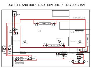
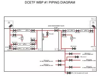
Explore the detailed piping diagram showing the crossconnect valve setup on Level A2/B2 for efficient water supply. This diagram includes various components such as valves, couplings, and connections, ensuring proper water distribution throughout the system. Stay informed about the configuration and functionality of the piping layout to facilitate maintenance and troubleshooting.

E N D
DCETF WBP #1 PIPING DIAGRAM PR 1 PR 4 PR 3 PR 5 PR 1 PR 2 PR 6 PR 2 0-2 LEVEL 0-2 LEVEL A2/B2 CROSSCONNECT VALVE 01-29-1 FM FM TF 01-24-7 TF 01-27-5 TF 01-33-1 TF 01-36-1 TF 01-30-1 TF 01-28-1 BH 3 TF 01-25-1 TF 01-30-3 PR 3 FPL 1-27-1 CW TF 01-24-3 TF 01-27-3 SW FPL 01-32-1 PIPING TO A1 TF 01-24-1 TF 01-27-1 01-24-5 JP-5 PIPING TO B1 PIPING TO A1 TF 01-31-11 A2 SPLIT SEAM COV FPL 01-31-7 TF 01-31-9 F1 SPLIT SEAM BH 1 COV TF 01-31-5 D1 SPLIT SEAM OH2 COV TF 01-31-1 D1 SPLIT SEAM OH1 COV TF 01-31-3 F1 SPLIT SEAM BH 2 COV FPL 1-32-1 (located on D1 Level)
DCETF WBP #1 PIPING DIAGRAM DCETF FIREMAIN COV A2/B2 BH DAMAGE WATER SUPPLY COV 1-29-1 TF 01-35-1 TF 01-31-1 TF 01-33-1 TF 01-26-1 TF 01-27-1 BH 1 BH 2 BH 3 BH 1 BH 2
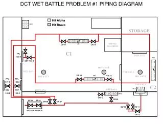
DCETF WBP #2 PIPING DIAGRAM PR 1 PR 1 PR 5 PR 3 PR 4 PR 2 0-2 LEVEL 0-2 LEVEL A2/B2 CROSSCONNECT VALVE 01-29-1 FM FM TF 01-24-7 TF 01-27-5 PR 6 TF 01-33-1 TF 01-36-1 TF 01-30-1 TF 01-28-1 BH 3 TF 01-25-1 TF 01-30-3 PR 3 FPL 1-27-1 PR 2 CW TF 01-24-3 TF 01-27-3 SW FPL 01-32-1 PIPING TO A1 TF 01-24-1 TF 01-27-1 01-24-5 JP-5 PIPING TO B1 PIPING TO A1 TF 01-31-11 A2 SPLIT SEAM COV FPL 01-31-7 TF 01-31-9 F1 SPLIT SEAM BH 1 COV TF 01-31-5 D1 SPLIT SEAM OH2 COV TF 01-31-1 D1 SPLIT SEAM OH1 COV TF 01-31-3 F1 SPLIT SEAM BH 2 COV FPL 1-32-1 (located on D1 Level)
DCETF WBP #2 PIPING DIAGRAM DCETF FIREMAIN COV A2/B2 BH DAMAGE WATER SUPPLY COV 1-29-1 TF 01-35-1 TF 01-31-1 TF 01-33-1 TF 01-26-1 TF 01-27-1 BH 2 BH 3 BH 1 BH 2 BH 1