Download

1 / 26
320 likes | 436 Views
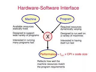
CSE 243: Introduction to Computer Architecture and Hardware/Software Interface. Execution of an instruction. Recall the steps involved in the execution of an instruction by a processor: Fetch an instruction from the memory. Fetch the operands. Execute the instruction. Store the results.

E N D
CSE 243: Introduction to Computer Architecture and Hardware/Software Interface
Execution of an instruction • Recall the steps involved in the execution of an instruction by a processor: • Fetch an instruction from the memory. • Fetch the operands. • Execute the instruction. • Store the results. • Several issues: • Where is the address of the memory location from which the present instruction is to be fetched? • Where is the present instruction stored while it is executed? • Where and what is the address of the memory location from which the data is fetched? • ...... • Basic processor architecture has several registers to assist in the execution of the instructions.
Basic processor architecture Address of the memory location to be accessed Memory Address of the next instruction to be fetched and executed. Data to be read into or read out of the current location MAR MDR Control R0 PC General purpose registers R1 IR ALU Instruction that is currently being executed R(n-1) - n general purpose registers Processor
Basic processor architecture (contd..) Data Path Control Path MAR MDR Processor • Control path is responsible for: • Instruction fetch and execution sequencing • Operand fetch • Saving results • Data path: • Contains general purpose registers • Contains ALU • Executes instructions Memory
Registers in the control path • Instruction Register (IR): • Instruction that is currently being executed. • Program Counter (PC): • Address of the next instruction to be fetched and executed. • Memory Address Register (MAR): • Address of the memory location to be accessed. • Memory Data Register (MDR): • Data to be read into or read out of the current memory location, whose address is in the Memory Address Register (MAR).
Fetch/Execute cycle • Execution of an instruction takes place in two phases: • Instruction fetch. • Instruction execute. • Instruction fetch: • Fetch the instruction from the memory location whose address is in the Program Counter (PC). • Place the instruction in the Instruction Register (IR). • Instruction execute: • Instruction in the IR is examined (decoded) to determine which operation is to be performed. • Fetch the operands from the memory or registers. • Execute the operation. • Store the results in the destination location. • Basic fetch/execute cycle repeats indefinitely.
Memory organization • Recall: • Information is stored in the memory as a collection of bits. • Collection of bits are stored or retrieved simultaneously is called a word. • Number of bits in a word is called word length. • Word length can be 16 to 64 bits. • Another collection which is more basic than a word: • Collection of 8 bits known as a “byte” • Bytes are grouped into words, word length can also be expressed as a number of bytes instead of the number of bits: • Word length of 16 bits, is equivalent to word length of 2 bytes. • Words may be 2 bytes (older architectures), 4 bytes (current architectures), or 8+ bytes (modern architectures).
Memory organization (contd..) • Accessing the memory to obtain information requires specifying the “address” of the memory location. • Recall that a memory has a sequenceof bits: • Assigning addresses to each bit is impractical and unnecessary. • Typically, addresses are assigned to a single byte. • “Byte addressable memory” • Suppose k bits are used to hold the address of a memory location: Size of the memory in bytes is given by: 2k where k is the number of bits used to hold a memory address. E.g., for a 16-bit address, size of the memory is 216= 65536 bytes What is the size of the memory for a 24-bit address?
Memory organization (contd..) Byte 0 • Memory is viewed as a sequence of • bytes. • Address of the first byte is 0 • Address of the last byte is 2k - 1, • where k is the number of bits used • to hold memory address • E.g. when k = 16, • Address of the first byte is 0 • Address of the last byte is 65535 • E.g. when k = 2, • Address of the first byte is ? • Address of the last byte is ? Byte 2k-1
Memory organization (contd..) Byte 0 Word #0 Byte 1 Consider a memory organization: 16-bit memory addresses Size of the memory is ? Word length is 4 bytes Number of words =Memory size(bytes)= ? Word length(bytes) Word #0 starts at Byte #0. Word #1 starts at Byte #4. Last word (Word #?) starts at Byte#? Byte 2 Byte 3 Byte 4 Word #1 Word #? Byte 65532 Byte 65533 Byte 65534 Byte 65535
Memory organization (contd..) Byte 0 Word #0 Byte 1 Byte 2 MAR Byte 3 Byte 4 MDR Word #1 MAR register contains the address of the memory location addressed Addr 65532 Byte 65532 Word #16383 Byte 65533 MDR contains either the data to be written to that address or read from that address. Byte 65534 Byte 65535
Memory operations • Memory read or load: • Place address of the memory location to be read from into MAR. • Issue a Memory_read command to the memory. • Data read from the memory is placed into MDR automatically (by control logic). • Memory write or store: • Place address of the memory location to be written to into MAR. • Place data to be written into MDR. • Issue Memory_write command to the memory. • Data in MDR is written to the memory automatically (by control logic).
Instruction types • Computer instructions must be capable of performing 4 types of operations. • Data transfer/movement between memory and processor registers. • E.g., memory read, memory write • Arithmetic and logic operations: • E.g., addition, subtraction, comparison between two numbers. • Program sequencing and flow of control: • Branch instructions • Input/output transfers to transfer data to and from the real world.
Instruction types (contd..) • Examples of different types of instructions in assembly language notation. • Data transfers between processor and memory. • Move A, B (B = A). • Move A, R1 (R1 = A). • Arithmetic and logic operation: • Add A, B, C(C = A + B) • Sequencing: • Jump Label(Jump to the subroutine which starts at Label). • Input/output data transfer: • Input PORT, R5 (Read from i/o port “PORT” to register R5).
Specifying operands in instructions • Operands are the entities operated upon by the instructions. • Recall that operands may have to be fetched from a memory location to execute an operation. • Memory locations have addresses using which they can be accessed. • Operands may also be stored in the general purpose registers. • Intermediate value of some computation which will be required immediately for subsequent computations. • Registers also have addresses. • Specifying the operands on which the instruction is to operate involves specifying the addresses of the operands. • Address can be of a memory location or a register.
Source and destination operands • Operation may be specified as: • Operation source1, source2, destination • An operand is called a source operand if: • It appears on the right-hand side of an expression • E.g., Add A, B, C(C = A+ B) • A and B are source operands. • An operand is called a destination operand if: • It appears on the left-hand side of an expression. • E.g., Add A, B, C (C = A + B) • C is a destination operand.
Source and destination operands (contd..) • In case of some instructions, the same operand serves as both the source and the destination. • Same operand appears on the right and left side of an expression. • E.g. Add A, B (B = A + B) • B is both the source and the destination operand. • Another classification of instructions is based on the number of operand addresses in the instruction.
Instruction types • Instructions can also be classified based on the number of operand addresses they include. • 3, 2, 1, 0 operand addresses. • 3-address instructions are almost always instructions that implement binary operations. • E.g. Add A, B, C(C = A + B) • k bits are used to specify the address of a memory location, then 3-address instructions need 3*k bits to specify the operand addresses. • 3-address instructions, where operand addresses are memory locations are too big to fit in one word.
Instruction types (contd..) • 2-address instructions one operand serves as a source and destination: • E.g.Add A, B (B = A + B) • 2-address instructions need 2*k bits to specify an instruction. • This may also be too big to fit into a word. • 2-address instructions, where at least one operand is a processor register: • E.g.Add A, R1 (R1 = A + R1) • 1-address instructions require only one operand. • E.g. Clear A (A = 0) • 0-address instructions do not operate on operands. • E.g.Halt (Halt the computer) • How are addresses of operands specified in the instructions?
Addressing modes • Different ways in which the address of an operand in specified in an instruction is referred to as addressing modes. • Register mode • Operand is the contents of a processor register. • Address of the register is given in the instruction. • E.g.Clear R1 • Absolute mode • Operand is in a memory location. • Address of the memory location is given explicitly in the instruction. • E.g. Clear A • Also called as “Direct mode” in some assembly languages • Register and absolute modes can be used to represent variables
Addressing modes (contd..) • Immediate mode • Operand is given explicitly in the instruction. • E.g.Move #200, R0 • Can be used to represent constants. • Register, Absolute and Immediate modes contained either the address of the operand or the operand itself. • Some instructions provide information from which the memory address of the operand can be determined • That is, they provide the “Effective Address” of the operand. • They do not provide the operand or the address of the operand explicitly. • Different ways in which “Effective Address” of the operand can be generated.
Addressing modes (contd..) Effective Address of the operand is the contents of a register or a memory location whose address appears in the instruction. Add (R1),R0 Add (A),R0 Main memory B Operand A B Register Operand B B R1 • Register R1 contains Address B • Address A contains Address B • Address B has the operand • Address B has the operand R1 and A are called “pointers” This is called as “Indirect Mode”
Addressing modes (contd..) Effective Address of the operand is generated by adding a constant value to the contents of the register • Operand is at address 1020 • Register R1 contains 1000 • Offset 20 is added to the • contents of R1 to generate the • address 20 • Contents of R1 do not change in the • process of generating the address • R1 is called as an “index register” Add 20(R1),R0 1000 offset = 20 Operand 1020 What address would be generated by Add 1000(R1), R0 if R1 had 20? 1000 R1 This is the “Indexing Mode”
Addressing Modes (contd..) Relative mode • Effective Address of the operand is generated by adding a constant value to the contents of the Program Counter (PC). • Variation of the Indexing Mode, where the index register is the PC • instead of a general purpose register. • When the instruction is being executed, the PC holds the address of the next instruction in the program. • Useful for specifying target addresses in branch instructions. Addressed location is “relative” to the PC, this is called “Relative Mode”
Addressing Modes (contd..) • Autoincrement mode: • Effective address of the operand is the contents of a register specified in the instruction. • After accessing the operand, the contents of this register are automatically incremented to point to the next consecutive memory location. • (R1)+ • Autodecrement mode • Effective address of the operand is the contents of a register specified in the instruction. • Before accessing the operand, the contents of this register are automatically decremented to point to the previous consecutivememory location. • -(R1) • Autoincrement and Autodecrement modes are useful for implementing “Last-In-First-Out” data structures.
Addressing modes (contd..) • Implicitly the increment and decrement amounts are 1. • This would allow us to access individual bytes in a byte addressable memory. • Recall that the information is stored and retrieved one word at a time. • In most computers, increment and decrement amounts are equal to the word size in bytes. • E.g., if the word size is 4 bytes (32 bits): • Autoincrement increments the contents by 4. • Autodecrement decrements the contents by 4.