Chapter 10 - Capacitors
Chapter 10 - Capacitors. Introductory Circuit Analysis Robert L. Boylestad. 10.1 – Introduction. Capacitor displays its true characteristics only when a change in voltage is made in the network. 10.2 – The Electric Field.

Chapter 10 - Capacitors
E N D
Presentation Transcript
Chapter 10 - Capacitors Introductory Circuit Analysis Robert L. Boylestad
10.1 – Introduction • Capacitor displays its true characteristics only when a change in voltage is made in the network.
10.2 – The Electric Field • The electric field is represented by electric flux lines, which are drawn to indicate the strength of the electric field at any point around the charged body. The denser the lines of flux, the stronger the electric field.
The Electric Field • The electric field strength at a point is the force acting on a unit positive charge at that point. • Electric flux lines always extend from a positively charged body to a negatively charged body, always extend or terminate perpendicular to the charged surface, and never intersect.
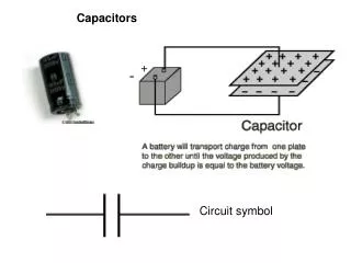
10.3 – Capacitance • A capacitor is constructed of two parallel conducting plates separated by an insulator. • Capacitance is a measure of a capacitor’s ability to store charge on its plates. • A capacitor has a capacitance of 1 farad (F) if 1 coulomb (C) of charge is deposited on the plates by a potential difference of 1 volt across its plates. • The farad is named after Michael Faraday, a nineteenth century English chemist and physicist.
Capacitance • The farad is generally too large a measure of capacitance for most practical applications, so the microfarad (106 ) or picofarad (1012 ) is more commonly used. • Different capacitors for the same voltage across their plates will acquire greater or lesser amounts of charge on their plates, hence the capacitors have greater or lesser capacitance.
Capacitance • Fringing – At the edge of the capacitor plates the flux lines extend outside the common surface area of the plates.
Capacitance • Dielectric – Insulator of the capacitor • The purpose of the dielectric is to create an electric field to oppose the electric field setup by free charges on the parallel plates. • Di for “opposing” and electric for “electric field” • Dipoles – Formed within the insulator of a capacitor when the electrons of the insulating material are unable to leave the parent atom and travel to the positive plate of the capacitor
Capacitance • With different dielectric materials between the same two parallel plates, different amounts of charge will deposit on the plates. • Permittivity – The ratio of the flux density to the electric field intensity in the dielectric. A measure of how easily the dielectric will “permit” the establishment of flux lines within the dielectric. • Relative permittivity – Often called the dielectric constant, it is the ratio of the permittivity of any dielectric to that of a vacuum.
Capacitance For every dielectric there is a potential that, if applied across the dielectric, will break the bonds within the dielectric and cause current to flow. The voltage required per unit length (electric field intensity) to establish conduction in a dielectric is an indication of its dielectric strength and is called the breakdown voltage
10.4 – Capacitors Types of Capacitors • Fixed – mica, ceramic, electrolytic, tantalum and polyester-film • Mica capacitor consists of mica sheets separated by sheets of metal foil. The plates are connected to two electrodes. The entire system is encased in a plastic insulating material. • The mica capacitor exhibits excellent characteristics under stress of temperature variations and high voltage applications.
Capacitors Electrolytic Capacitors • Most commonly used in situations where capacitances of the order of one to several thousand microfarads are required. • Primarily for use in dc networks because they have good insulating characteristics (high leakage current) between the plates in one direction but take on the characteristics of a conductor in the other direction. • Basic construction consists of a roll of aluminum foil coated on one side with an aluminum oxide, the aluminum being the positive plate and the oxide the dielectric. A layer of paper or gauze saturated with an electrolyte is placed over the aluminum oxide on the positive plate. Another layer of aluminum without the oxide is then placed over this layer to assume the role of the negative plate.
Capacitors Polyester-film Capacitors • Basic construction consists of two metal foils separated by a strip of polyester material such as Mylar. The outside layer of polyester is applied to act as an insulating jacket. • Each metal jacket is connected to a lead that extends either axially or radially from the capacitor. • The rolled construction results in a large surface, and the use of the plastic dielectric results in a very thin layer between the conducting surfaces. • The capacitor can be used for both dc and ac networks.
Capacitors Ceramic Capacitors • Made in different shapes and sizes but the basic construction is the same • A ceramic base is coated on both sides with a metal, such as copper or silver, to act as the two plates. The leads are then attached through electrodes to the plates. An insulating coating of ceramic or plastic is then applied over the plates and dielectric. • Ceramic capacitors have very low leakage current and can be used in both dc and ac networks.
Capacitors • Working voltage – the voltage that can be applied across a capacitor for long periods of time with out breakdown • Surge voltage – The maximum dc voltage that can be applied for a short period of time • Leakage current – The current that results in the total discharge of a capacitor as the capacitor is disconnected from the charging network for a sufficient length of time.
Capacitors Variable Capacitors • Most common are shown in the figure below. The dielectric for each is air. The capacitance is changed by turning the shaft at one end to vary the common area of the movable and fixed plates. The greater the common area the larger the capacitance.
Capacitors Measuring and testing • The digital reading capacitance meter shown will allow you to simply place the capacitor between the provided clips with the proper polarity and the meter will display the level of capacitance. Insert Fig 10.20
10.5 – Transients in Capacitive Networks: Charging Phase • The placement of charge on the plates of a capacitor does not occur instantaneously. • Transient Period – A period of time where the voltage or current changes from one steady-state level to another. • The current ( ic ) through a capacitive network is essentially zero after five time constants of the capacitor charging phase.
10.7 – Initial Conditions • The voltage across a capacitor at the instant of the start of the charging phase is called the initial value. Once the voltage is applied the transient phase will commence until a leveling off occurs after five time constants called steady-state as shown in the figure.
10.8 – Instantaneous Values • To determine the voltage (or current) at a particular instant of time that is not an integral multiple of the time constant () • Charging: • Discharging:
10.9 – Thévenin Equivalent : = RThC • In a network that is not a simple series form, it will be necessary to first find the Thévenin equivalent circuit for the network external to the capacitive element. • Using ETh as the source voltage and RTh as the resistance, the time constant is = RThC.
10.10 – The Current ic • Current ic associated with the capacitance C is related to the voltage across the capacitor by • Where dvc / dt is a measure of the change in vc in a vanishingly small period of time. • The function dvc / dt is called the derivative of the voltage vc with respect to time t.
10.11 – Capacitors in Series and Parallel • Capacitors, like resistors, can be placed in series and in parallel. • When placed in series, the charge is the same on each capacitor.
Capacitors in Series and Parallel • Placing capacitors in parallel the voltage across each capacitor is the same. • The total charge is the sum of that on each capacitor.
10.12 – Energy Stored by a Capacitor • The ideal capacitor does not dissipate any energy supplied to it. It stores the energy in the form of an electric field between the conducting surfaces. • The power curve can be obtained by finding the product of the voltage and current at selected instants of time and connecting the points obtained. • WC is the area under the curve.
10.13 – Stray Capacitance • Stray capacitances exist not through design but simply because two conducting surfaces are relatively close to each other. • Two conducting wires in the same network will have a capacitive effect between them.
10.14 – Applications • Capacitors find applications in: • Electronic flash lamps for cameras • Line conditioners • Timing circuits • Electronic power supplies