Guide Wire Failure Analysis
Guide Wire Failure Analysis. Brad James, Ph.D., P.E. Background. 304 stainless steel guidewire fractured after percutaneous balloon dilation of the pulmonary artery After successfully crossing lesion and dilation, the Doctor reported the wire became caught

Guide Wire Failure Analysis
E N D
Presentation Transcript
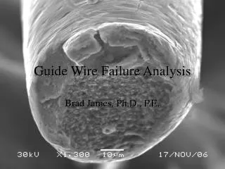
Guide Wire Failure Analysis Brad James, Ph.D., P.E.
Background • 304 stainless steel guidewire fractured after percutaneous balloon dilation of the pulmonary artery • After successfully crossing lesion and dilation, the Doctor reported the wire became caught • Attempts to remove the wire were unsuccessful • Ultimately, guide wire fractured approximately 5 cm from the distal tip • Remaining wire end remained in patient • Patient remained “asymptomatic”
Background • The wire was sent to a metallurgical laboratory for examination • The laboratory found an inclusion on the fracture surface and indicated the inclusion acted as a “stress riser and reduced the cross-sectional area” • Tensile tests of other sections of the subject guidewire indicated a “significant range of ductility from fairly ductile to brittle”
Fracture Surface Analysis • SEM analysis of subject break indicated ductile overload with microvoid coalescence • Inclusion with shear lips toward top edge at 12:00 • Inclusion was roughly round, approximately 1/15th of wire diameter • Rub observed on outside edge of fracture surface
Inclusion Analysis • Inclusion contained primarily silicon, carbon, and oxygen • Note shear lips around inclusion
Tensile Sample Analysis • Three tensile test samples were also supplied • Visual inspection indicated each sample broke in the grips • SEM analysis indicated ductile fracture (but not classic “cup and cone”
Failure Analysis • Inclusion equal to approximately 1/15 the diameter of the wire (area fraction of approximately 0.4%) • Inclusions tend to have low interfacial bonding strength with matrix, therefore little difference between inclusions and pores • In ductile materials, plastic deformation reduces stress concentration at notches • Ductile materials also exhibit notch strengthening: notch strength = max tensile load/area at notch • Conservative assumption for this example is no notch strengthening, wire strength reduced by reduction in area
Failure Analysis • With no notch strengthening, wire strength reduced by area reduction (0.4%) • Specified wire tensile strength was 405 to 435 ksi • Assuming subject wire strength was 420 ksi (middle of range), inclusion reduced tensile strength by approximately 1.7 ksi.
Failure Analysis Inclusion was near outside edge of fracture, inside shear lip area, away from initiation location
Conclusions • The subject guidewire fractured in a ductile manner when service loads exceeded it’s tensile strength • Inclusion reduced strength of wire, but only by a miniscule amount (well within specifications) • Variations in apparent ductility from tensile testing (measured by elongation) only occurred because of the test methods employed • SEM examination indicated each of the fractures were ductile in nature, no evidence of “brittle fracture” was observed