Developments in EMT Simulation
Developments in EMT Simulation. Nick Barlow University of Bristol EMT software workshop 11/19/01. Outline. Database config. objects Background mixing Double peak in L1Accept time The future…. Getting Ax parameters out of database.

Developments in EMT Simulation
E N D
Presentation Transcript
Developments in EMT Simulation Nick Barlow University of Bristol EMT software workshop 11/19/01
Outline • Database config. objects • Background mixing • Double peak in L1Accept time • The future…..
Getting Ax parameters out of database • AX parameters include tower mask, FIR constants, M,G,E,X,Y thresholds, time alignment • In <= 10 series releases, the AX parms used are default values specified in L1EmtSim/L1EmtAxParms.cc • Can also be overwritten via tcl (tcl parameters belong to L1EmtSimModule) • Can now use AxRecord out of database • L1EmtBuildEnv called from L1TOepSimEnvSequence, puts proxy for L1EmtAxRecord into the event • L1EmtSimModule takes this out of event, puts into an L1EmtAx • Which L1EmtAxRecord to be used is controlled by tcl parameters aliasList and configAlias – can either use monthly config alias from “top” alias list or e.g. PHYSICS alias from “orc” alias list. • Can have phi-dependent AX parms – as in real EMT
Background mixing • In releases < 11.6.0, SimAppProduction sequence was • EmcSim converts GHits into 64 clk4 tick waveforms used as input to L1EmtSim • EmcSim later converts cyclic background digis to waveforms and mixes these with existing waveforms • L1EmtSim doesn’t see any background
Background mixing • In releases >=11.6.0, the waveforms from simulated GHits and background digis are mixed before the L1 trigger stage • EMC GHits and digis just contain a peak energy and a peak time – different tags of EMC sim deal with the background digis in different ways… either: • convert to waveform in same way as is done for Ghits • look up stored waveform with same energy and time
Background mixing • If both DCT and EMT simulations are to see background, we want to get timing right so real background tracks are treated realistically • Use empty Bogus collection () as SimAppInputCollection • Use data bhabha collection as SimAppBkndInputCollection • Want peak to be in same place as when the bhabha collection is reconstructed normally • Can move by adjusting tcl parameters in EmcDigisToWaveform
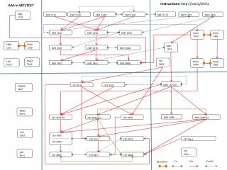
Multiple layers of background • It is possible to mix more than one cyclic background event per generated MC event • For the EMC this was done in EvtMixEmcSequence by calling EmcDigisToWaveform and EmcMixWaveform N times Problem – D2*+ and other lines go down significantly. High background in the EMT causes early triggers – tracks fall outside DCT window Plotting Fct trigger lines for MC dimuon events with 1, 2, 3, and 4 layers of cyclic background: 3A&2A&2M 3A&B* 3B&B*&1G 2E EM* G* D2&1E 1Y&1B D2*+ 3M&D2 4M 3M&M* 2M&A+ M*&5U 2BM&2M 1Y 3M 3B&2A M*&1B D2&1M 2M D2 1B 1M Black = 1*bg Red = 2*bg Green = 3*bg Blue = 4*bg
Multiple layers of background • The cause of the excessive background in EMT is a problem first identified by David Stoker in April • For each layer n (= 1 .. Nmixers) of background: • EmcDigisToWaveform_n takes cyclic background digis, converts them to waveforms, and appends them to noiseWaveformList • EmcMixWaveforms_n mixes noiseWaveformList with the waveform list from GHits to produce output waveform list • Therefore, nth layer of background is added Nmixers – n +1 times • This bug has been fixed in the latest tags of EvtMix, by only calling EmcMixWaveforms once per MC event, after all the calls to EmcDigisToWaveforms Black = 1*bg Red = 2*bg Green = 3*bg Blue = 4*bg Magenta=5*bg 3A&2A&2M 3A&B* 3B&B*&1G 2E EM* G* D2&1E 1Y&1B D2*+ 3M&D2 4M 3M&M* 2M&A+ M*&5U 2BM&2M 1Y 3M 3B&2A M*&1B D2&1M 2M D2 1B 1M
Double peak in L1Accept time • For a long time, a double peak structure has been seen in BunchT0 for MC bhabha events • This is not seen in data • This is seen to a lesser extent in MC dimuon events and is hardly visible in multihadron events • Bhabha triggers are dominated by EMT-only lines (2E and EM*) • Dimuon and multihadron events have more DCT-only and mixed lines; L1A time comes mainly from DCT • Points to a problem with EMT simulation
Double peak in L1Accept time analysis-8 (=10.0.1) 10.2.3+tags 8.8.1b (Geant3) 11.3.0a 2 peaks seem to be ~1 clk 8 tick apart
Double peak in L1Accept time • Look for any theta or phi dependence • Phi sectors 13-21 have different FIR constants to compensate for different shaping times in EMC pre-amps – (probably not simulated) – could that cause this? • Seems very unlikely – problem has been there since before phi-dependent AX parameters were put into EMT simulation…
Double peak in L1Accept time • Could L1EmtSim/L1EmtSpy be performing the EMT algorithm incorrectly? • In particular the clk4 to clk 8 transition • FIR constants are applied in clk4, zero cross is in clk 8 • Check output of sim at various stages against output of L1EmtSpy/L1EmtSpyModel – independent model of EMT algorithm • Make L1EmtSpyModel object from L1EmtSpy/L1EmtSpySector, with the L1EmtHistory<d_Ushort> containing phi sum after NN and the L1EmtAx being used in the simulation • Can compare outputs at each stage of algorithm – e.g. FIR output, zero cross position, output map • Checked ~10 events*40 sectors*64 ticks in this way, and about 30 other events checking just the output maps
MixedEvtCounter: processing event # 2 Doing AX sim for sector 22 L1EmtSpyModel: zx at: 80 L1EmtSpyModel: M at 75 L1EmtSpyModel: M at 76 L1EmtSpyModel: M at 77 L1EmtSpyModel: M at 78 Doing AX sim for sector 23 L1EmtSpyModel: zx at: 81 L1EmtSpyModel: M at 75 L1EmtSpyModel: G at 75 L1EmtSpyModel: M at 76 L1EmtSpyModel: G at 76 L1EmtSpyModel: M at 77 L1EmtSpyModel: G at 77 L1EmtSpyModel: M at 78 MixedEvtCounter: processing event # 1 Doing AX sim for sector 9 L1EmtSpyModel: zx at: 82 L1EmtSpyModel: M at 77 L1EmtSpyModel: G at 77 L1EmtSpyModel: E at 77 L1EmtSpyModel: M at 78 L1EmtSpyModel: G at 78 L1EmtSpyModel: E at 78 L1EmtSpyModel: M at 79 L1EmtSpyModel: G at 79 L1EmtSpyModel: E at 79 Doing AX sim for sector 10 L1EmtSpyModel: zx at: 82 L1EmtSpyModel: M at 77 L1EmtSpyModel: G at 77 L1EmtSpyModel: E at 77 L1EmtSpyModel: M at 78 L1EmtSpyModel: G at 78 L1EmtSpyModel: E at 78 L1EmtSpyModel: M at 79 L1EmtSpyModel: G at 79 L1EmtSpyModel: E at 79 L1EmtAxSim sector 22:- zeroCrossing[22-133] at bin 80 outputSectorMap[38-133]= M:75-78 L1EmtAxSim sector 23:- zeroCrossing[22-133] at bin 81 outputSectorMap[38-133]= M:75-78 G:75-77 L1EmtAxSim sector 9:- zeroCrossing[22-133] at bin 82 outputSectorMap[38-133]= M:77-79 G:77-79 E:77-79 Y:77-79 L1EmtAxSim sector 10:- zeroCrossing[22-133] at bin 82 outputSectorMap[38-133]= M:77-79 G:77-79 E:77-79 Y:77-79 Double peak in L1Accept time • Found NO discrepancies between output of simulation and L1EmtSpyModel !!!
Double peak in L1Accept time • Use L1FctSim/L1FctPrintDigi to see in output of SimApp the L1Accept time and which trigger lines fired… • Try to look for pattern in which events end up with L1Accept time < -620ns (1st peak) or > -620ns (2nd peak) MixedEvtCounter: processing event # 3 [ 1d:ffffffff:0001e1/d26e433b:X ] L1EmtGltDigi has 134 samples starting at BX -2089 E: 4:77-79 5:77-79 14:77-79 G: 4:77-79 5:77-79 14:77-79 M: 4:77-79 5:77-79 13:77-80 14:77-79 trgEMPrintGL; Number of phi towers 20 Cluster types 5 Expected trigger tick 0 -3 M Phi 0 0 0 0 1 1 0 0 0 0 0 0 0 1 1 0 0 0 0 0 -3 G Phi 0 0 0 0 1 1 0 0 0 0 0 0 0 0 1 0 0 0 0 0 -3 E Phi 0 0 0 0 1 1 0 0 0 0 0 0 0 0 1 0 0 0 0 0 -3 X Phi 0 0 0 0 0 0 0 0 0 0 0 0 0 0 0 0 0 0 0 0 -3 Y Phi 0 0 0 0 0 0 0 0 0 0 -2 M Phi 0 0 0 0 1 1 0 0 0 0 0 0 0 1 1 0 0 0 0 0 -2 G Phi 0 0 0 0 1 1 0 0 0 0 0 0 0 0 1 0 0 0 0 0 -2 E Phi 0 0 0 0 1 1 0 0 0 0 0 0 0 0 1 0 0 0 0 0 -2 X Phi 0 0 0 0 0 0 0 0 0 0 0 0 0 0 0 0 0 0 0 0 -2 Y Phi 0 0 0 0 0 0 0 0 0 0 -1 M Phi 0 0 0 0 1 1 0 0 0 0 0 0 0 1 1 0 0 0 0 0 -1 G Phi 0 0 0 0 1 1 0 0 0 0 0 0 0 0 1 0 0 0 0 0 -1 E Phi 0 0 0 0 1 1 0 0 0 0 0 0 0 0 1 0 0 0 0 0 -1 X Phi 0 0 0 0 0 0 0 0 0 0 0 0 0 0 0 0 0 0 0 0 -1 Y Phi 0 0 0 0 0 0 0 0 0 0 0 M Phi 0 0 0 0 0 0 0 0 0 0 0 0 0 1 0 0 0 0 0 0 0 G Phi 0 0 0 0 0 0 0 0 0 0 0 0 0 0 0 0 0 0 0 0 0 E Phi 0 0 0 0 0 0 0 0 0 0 0 0 0 0 0 0 0 0 0 0 0 X Phi 0 0 0 0 0 0 0 0 0 0 0 0 0 0 0 0 0 0 0 0 0 Y Phi 0 0 0 0 0 0 0 0 0 0 L1FctDigi time= 12/31/97 23:59:59 (local time) 123456789 ns (absolute) FctDigi lines= 20856 Trigger 00011110100010100000000000000000 floatTime= -709.984 ns MixedEvtCounter: processing event # 5 [ 1d:ffffffff:0001e1/d26e4a0d:K ] L1EmtGltDigi has 134 samples starting at BX -2128 E: 5:79-81 6:78-81 16:79-81 G: 5:79-81 6:78-81 16:79-81 M: 3:78-81 4:78-81 5:79-81 6:78-81 15:78-81 16:79-81 trgEMPrintGL; Number of phi towers 20 Cluster types 5 Expected trigger tick 0 -3 M Phi 0 0 0 1 1 0 1 0 0 0 0 0 0 0 0 1 0 0 0 0 -3 G Phi 0 0 0 0 0 0 1 0 0 0 0 0 0 0 0 0 0 0 0 0 -3 E Phi 0 0 0 0 0 0 1 0 0 0 0 0 0 0 0 0 0 0 0 0 -3 X Phi 0 0 0 0 0 0 0 0 0 0 0 0 0 0 0 0 0 0 0 0 -3 Y Phi 0 0 0 0 0 0 0 0 0 0 -2 M Phi 0 0 0 1 1 1 1 0 0 0 0 0 0 0 0 1 1 0 0 0 -2 G Phi 0 0 0 0 0 1 1 0 0 0 0 0 0 0 0 0 1 0 0 0 -2 E Phi 0 0 0 0 0 1 1 0 0 0 0 0 0 0 0 0 1 0 0 0 -2 X Phi 0 0 0 0 0 0 0 0 0 0 0 0 0 0 0 0 0 0 0 0 -2 Y Phi 0 0 0 0 0 0 0 0 0 0 -1 M Phi 0 0 0 1 1 1 1 0 0 0 0 0 0 0 0 1 1 0 0 0 -1 G Phi 0 0 0 0 0 1 1 0 0 0 0 0 0 0 0 0 1 0 0 0 -1 E Phi 0 0 0 0 0 1 1 0 0 0 0 0 0 0 0 0 1 0 0 0 -1 X Phi 0 0 0 0 0 0 0 0 0 0 0 0 0 0 0 0 0 0 0 0 -1 Y Phi 0 0 0 0 0 0 0 0 0 0 0 M Phi 0 0 0 1 1 1 1 0 0 0 0 0 0 0 0 1 1 0 0 0 0 G Phi 0 0 0 0 0 1 1 0 0 0 0 0 0 0 0 0 1 0 0 0 0 E Phi 0 0 0 0 0 1 1 0 0 0 0 0 0 0 0 0 1 0 0 0 0 X Phi 0 0 0 0 0 0 0 0 0 0 0 0 0 0 0 0 0 0 0 0 0 Y Phi 0 0 0 0 0 0 0 0 0 0 trgDCDchDigis:number of digis in event=277 NICK1: BX at L1A is: -128 L1FctDigi time= 12/31/97 23:59:59 (local time) 123456789 ns (absolute) FctDigi lines= 285560 Trigger 00011110110110100010000000000000 floatTime= -537.715 ns
Double peak in L1Accept time • Events seem to fall in left hand peak when ‘expected tick’ does not match ‘actual’ tick • Where does ‘expected trigger tick’ come from???
Double peak in L1Accept time • Interface between EMT and GLT simulation is through L1EmtSim/L1EmtSimDigiToTrgEM • Calls several trgEM functions in trgDC • In beginJob() – calls trgEMCenterGL with argument 0 • This is what translates into ‘expected trigger tick 0’ • In event() – calls trgEMPointGL(nstart,nsamples,msim,gsim etc.) 2d arrays of M,G,E etc. objects in phi and time = (tick at 1st sample of L1EmtGltSimDigi)minusoffset usually –64 or –65= 16 = no. samples in L1EmtGltSimDigi =134 (1st 6 are always 0) trgEMPointGL fills the trgEM_GL common block in trgDC
Double peak in L1Accept time • So, arrays in trgEM start counting from ~ -80 or -81, depending on which BX the L1EmtGltSimDigi starts from BUT nTrgCenterEM is always 0. • Only function which uses both nTrgCenterEM and the trgEM_GL common block is trgGLTickDelay • Thought I had found something funny in there the other day – everywhere else where tickAtBX is used, first argument is 5 (this is ‘speed’ in FcsClock::tickAtBx; 25 bunch crossings per clk8??) but in trgGLTickDelay it calls this function with speed 6 • Tried changing this to 5…
Double peak in L1Accept time • Try calling trgEMCenterGL with argument 2 • nTrgCenterEM’expected trigger time’ • Moves L1A time by ~2 ticks! • Why is nTrgCenterEM used at all?
The future… Other (minor) things… • Fixed memory leak in L1EmtSim/L1EmtAxParms • Removed all mentions of xdr files and AppFileInputModule as part of Geant 3 deprecation • Fix double peak problem • Figure out what’s going on in trgGLTickDelay… • Teach Mark everything I know about EMT simulation • Document everything • Write thesis…